Bending rotation device used for bending steel pipe

A bending and turning technology, which is applied in the field of bending devices, can solve the problems of hard corners, cracks, and affecting internal fluid circulation, etc., and achieve the effect of increasing the bending length

Inactive Publication Date: 2015-06-10
DALIAN YUREN DESIGN
View PDF0 Cites 2 Cited by
  • Summary
  • Abstract
  • Description
  • Claims
  • Application Information

AI Technical Summary

Problems solved by technology

[0002] At present, the curved pipe is generally turned by tightening one end of the straight pipe and then twisting the other end. Such a turning requires a very precise grasp of the twist, otherwise the straight pipe will directly crack or bend into a hard angle. I

Method used


Image

  • Bending rotation device used for bending steel pipe
  • Bending rotation device used for bending steel pipe

Examples


Embodiment Construction

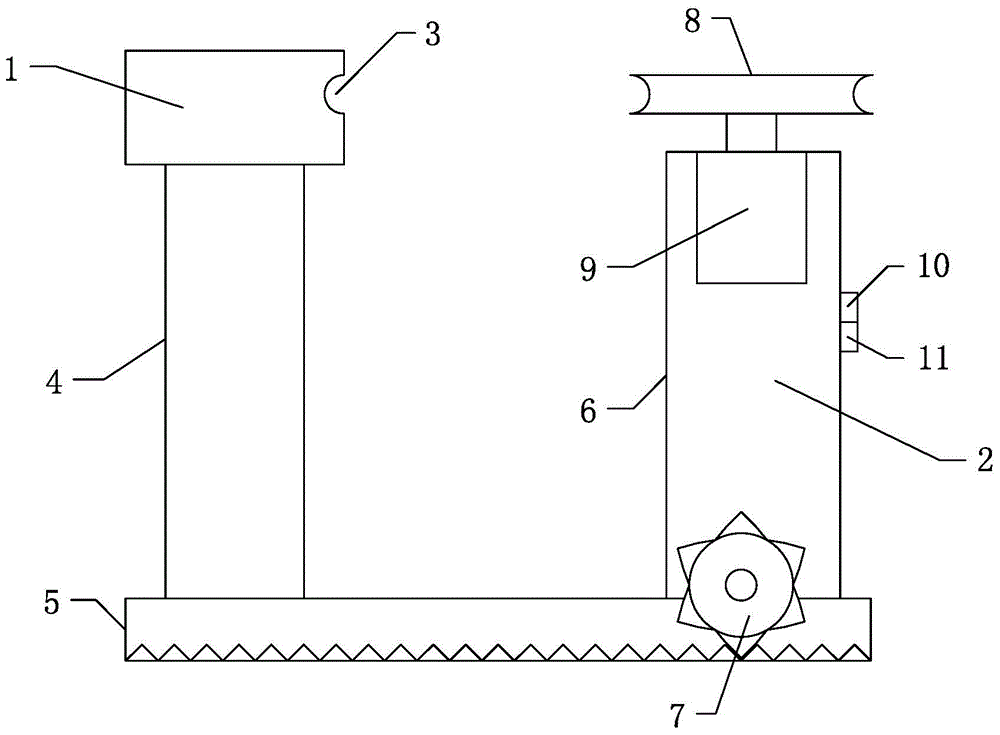
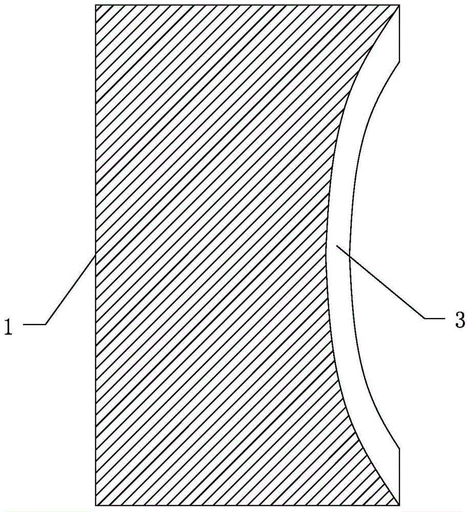
[0019] Such as figure 1 with figure 2 Shown is a bending device for bending steel pipes, a bending seat 1 and a bending wheel 2;

[0020] The surface of the bending seat 1 near the bending wheel 2 is processed with a bending groove 3 with a semicircular cross-section and an arc-shaped extending direction;

[0021] The bending seat 1 is fixed on the ground through the column 4;

[0022] The column 4 is laterally fixed with a guide rail 5, and the inner wall of the guide rail 5 is provided with teeth;

[0023] The bending wheel 2 includes: a supporting body frame 6, a travel gear 7 and a rotating wheel 8 fixed to the lower end of the supporting body frame 6 and meshed with the teeth on the inner wall of the guide rail 5;

[0024] The rotary wheel 8 is a disc with a semicircular cross-section processed radially on the circumferential side wall;

[0025] Adopt the present invention of above-mentioned technical scheme, at first put the straight pipe into the bending groove 3, ...


PUM


Abstract

The invention discloses a bending rotation device used for bending a steel pipe. The bending rotation device comprises a bending seat and a bending rotary wheel, wherein a bending groove having a semi-round cross section and extending in an arc shape is formed in the surface, close to the bending rotary wheel, of the bending seat; a stand column is transversely fixed with a guide rail, and teeth are arranged on an inner wall of the guide rail; the bending rotary wheel comprises a supporting body frame, a traveling gear fixed at a lower end of the supporting body frame and meshed with the teeth of the inner wall of the guide rail, and a rotary wheel; the rotary wheel is a disc with a semi-round cross section in a radial direction of a circumferential side wall. With the adoption of the technical scheme, firstly, a straight pipe is fitly put into the bending groove, that is to say, the straight pipe serves as a chord of a side edge of the bending groove; secondly, the rotary wheel is started until a groove of the rotary wheel is clung to an outer wall of the straight pipe; thirdly, the rotary wheel is further driven to extrude the straight pipe until the straight pipe is basically clung to the bending groove; fourthly, the rotary wheel is started for rotation, so that the straight pipe can be continuously rolled and extruded, and the bending length is continuously increased.

Description

technical field [0001] The invention relates to a bending device for bending steel pipes. Background technique [0002] At present, the bending pipe is generally realized by tightening one end of the straight pipe and then twisting the other end. Such a bending requires a very precise grasp of the twist, otherwise the straight pipe will directly crack or bend into a hard angle. If there is a hard angle, the pipe will be damaged The inner diameter of the straight pipe will become smaller and affect the circulation of the internal fluid, so it is necessary to develop a steel pipe bending device that can avoid hard angles and cracks in straight pipes. Contents of the invention [0003] Aiming at the above technical problems, the present invention proposes a steel pipe bending device capable of avoiding hard corners and cracks in straight pipes. [0004] In order to achieve the above purpose, it is realized through the following technical solutions: [0005] A bending device...

Claims


Application Information

Patent Timeline
IPC IPC(8): B21D7/00
CPCB21D7/00
Inventor 骆斌
Owner DALIAN YUREN DESIGN
Why Eureka
Try Eureka