Thermal magnetic tripping device and circuit breaker thereof

A technology of thermal magnetic tripping and circuit breaker, applied in the direction of protection switch operation/release mechanism, etc., can solve the problem of low bending stability of bimetals, and achieve the effect of improving bending rate, preventing contact, and increasing bending length

Pending Publication Date: 2019-07-05
ZHEJIANG TENGEN ELECTRIC
View PDF0 Cites 0 Cited by
  • Summary
  • Abstract
  • Description
  • Claims
  • Application Information

AI Technical Summary

Problems solved by technology

[0004] Therefore, the technical problem to be solved by the present invention is to overcome the defect of low bending stability of the bimetal strip in the thermal-magnetic tripping device in the prior art, thereby providing a thermal-magnetic tripping device and its circuit breaker

Method used


Image

  • Thermal magnetic tripping device and circuit breaker thereof
  • Thermal magnetic tripping device and circuit breaker thereof
  • Thermal magnetic tripping device and circuit breaker thereof

Examples


specific Embodiment approach

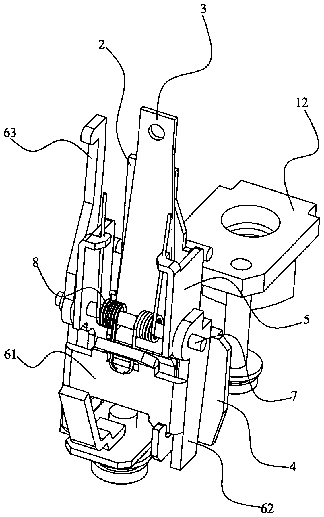
[0054] Such as Figure 1 to Figure 5 A specific implementation of the thermal-magnetic tripping device shown includes:

[0055] Conductor 1.

[0056] The heating element 2 is connected with the conductive member 1 to make the heating element 2 generate heat.

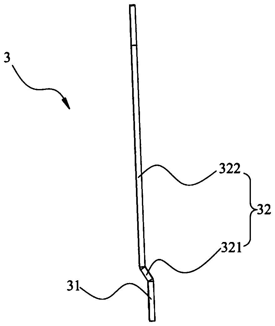
[0057] The bimetal 3 includes a fixed part 31 and a movable part 32 connected to the fixed part 31, the fixed part 31 is fixedly connected to the thermal element 2, and the movable part 32 is arranged opposite to the thermal element 2 The fixed part 31 receives the heat of the heating element 2 to bend and deform the movable part 32, so that the end of the movable part 32 away from the fixed part 31 drives the draw bar 9 of the circuit breaker to rotate.

[0058] The magnetic tripping mechanism is fixedly connected with the thermal element 2 and the bimetal strip 3, and is used to drive the draw bar 9 of the circuit breaker to rotate.

[0059] The thermal-magnetic tripping device above includes a conductive part 1, a ...

Embodiment 2

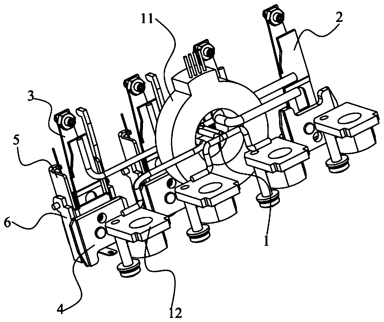
[0082] Such as Figure 1 to Figure 7 A specific implementation of the circuit breaker includes the thermal-magnetic tripping device described in Embodiment 1, which can make the bimetal 3 in the circuit breaker have good bending stability, and then make the thermal-magnetic tripping device The stability is better.

[0083] Such as Image 6 As shown, the circuit breaker also includes a housing 10 and a magnetic ring 11 disposed in the housing 10, the thermal-magnetic tripping device is disposed in the housing 10, and the conductive member 1 is located in the magnetic ring 11, and one end protrudes from the magnetic ring 11 to connect with the connecting plate 12, and the magnetic ring 11 is located between the connecting plate 12 and the static iron core 4.

[0084] In the prior art, the conductive parts in the circuit breaker with low rated current are directly connected to the bimetal, causing the bimetal sheet to heat and bend. This kind of circuit breaker with low rated c...


PUM


Abstract

The invention provides a thermal magnetic tripping device and a circuit breaker thereof. The thermal magnetic tripping device comprises the following steps of a conductive member; a thermal element connected to the conductive member to make the thermal element generate heat; a bimetallic strip comprising a fixed portion and a movable portion connected to the fixed portion, wherein the fixed portion is fixedly connected to the heat element, the movable portion is disposed opposite to the heat element at interval, and the fixed portion receives the heat of the heat element to bend and deform themovable portion and to make one end of the movable portion away from the fixed portion drive the drawbar of the circuit breaker to rotate; and a magnetic tripping mechanism fixedly connected to the heat element and the bimetallic strip for driving the drawbar of the circuit breaker to rotate. The above thermal magnetic tripping device can fix the thermal bending deformation position of the bimetallic strip such that the bimetallic strip can have the same bending length, the same degree of bending, the same bending speed, and the consistency of the bending time at the same current, thereby improving the bending stability of the bimetallic strip and increasing the specific bending rate of the bimetallic strip.

Description

technical field [0001] The invention relates to the technical field of low-voltage electrical appliances, in particular to a thermal-magnetic tripping device and a circuit breaker thereof. Background technique [0002] Thermal-magnetic trip units provide both magnetic and thermal protection. Magnetic protection means that when the current is large enough, the magnetic field force generated overcomes the reaction force spring to attract the moving iron core to strike the drawbar, thereby driving the operating mechanism to cut off the circuit; thermal protection means that the thermal element heats up when the current passes through the thermal magnetic tripping device , The bimetal sheet is heated and deformed. When the deformation reaches a certain level, the traction rod is hit to drive the operating mechanism to cut off the circuit. [0003] Both the heat element and the bimetal sheet in the prior art are of a straight plate type, the heat element is attached to the bimet...

Claims


Application Information

Patent Timeline
Patent Type & Authority Applications(China)
IPC IPC(8): H01H71/40
CPCH01H71/40
Inventor 胡浪涛张亦威张洁吴燕平杨启勇陈丰飞王兴利刘向宇
Owner ZHEJIANG TENGEN ELECTRIC
Why Eureka
Try Eureka