

Optical fiber sensing device waveform grooves and cylinder body
An optical fiber sensing and wave groove technology, which is applied in the direction of measuring the changing force of optical properties of materials when they are stressed, can solve the problems of limiting the popularization and use of optical fiber sensors, defects in anti-interference ability, and narrow application range, and achieves Excellent environmental adaptability, flexible use, and the effect of expanding the scope of use
Inactive Publication Date: 2012-12-19
XIAN JINHE OPTICAL TECH
View PDF9 Cites 1 Cited by
- Summary
- Abstract
- Description
- Claims
- Application Information
AI Technical Summary
Problems solved by technology
[0002] Due to the need for landslides, debris flows, earthquakes, and the health monitoring of large artificial buildings, stress parameter monitoring is one of the most important parameters that technicians care about. Defects in aspects lead to a relatively narrow scope of application
With the in-depth understanding of optical fiber and the development of optical fiber technology, more and more scholars tend to use optical fiber technology solutions for point and distributed monitoring of stress, Chinese patent application number 200410073021. Fiber Optic Sensor Embedding and Testing Method” patent document, proposed a serpentine micro-bend optical fiber sensor composed of multi-section short sleeves containing optical fibers, and micro-bending points are formed between the sleeves. Compared with traditional sensors, Its advantages are anti-electromagnetic interference, suitable for detection of various rock masses, high test accuracy, and distributed monitoring can be realized. However, in this scheme, the bending curvature of the micro-bending points formed between casings is random and may be large. , or it may be small. When the curvature is too small, the strength of the optical fiber will be affected, and even break soon, resulting in the failure of the sensing device. In addition, the protection of the optical fiber at the micro-bending point is obviously insufficient, but if the protection is strengthened, It may lose the condition of micro-bending detection, or require special devices for protection, which will increase the cost virtually
These have all limited the popularization and use of the optical fiber sensor of this invention
Method used
View moreImage
Smart ImageViewing Examples

Examples
Embodiment 1
Embodiment 2
Embodiment 3
Login to View More PUM
 Abstract
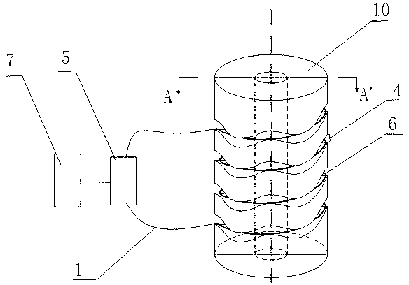
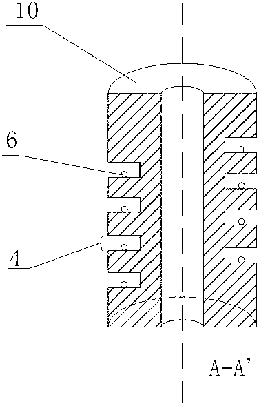
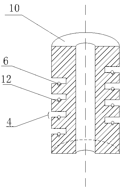
The invention discloses an optical fiber sensing device with waveform grooves and a cylinder body, wherein the waveform grooves (4) are distributed on the cylinder body (10); wave crests and wave troughs which are staggered and corresponded to each other are arranged on two opposite planes of the waveform grooves (4); and a first signal optical fiber (6) is arranged between wave crests on two opposite planes of the waveform grooves (4). When the cylinder body (10) is deformed under stress, the distance between wave crests at two opposite sides inside the waveform grooves (4) on the cylinder body (10) is changed, then a bending curvature of the first optical fiber (6) arranged between the wave crests is changed, so that the bending loss of the first optical fiber (6) is changed; the stress on the cylinder body (10) can be calculated through a testing unit (5) and a processing unit (7); and a novel sensing device is formed through the organic combination of the cylinder body (10) and the micro-bending waveform grooves (4).
Description
technical field [0001] The invention belongs to an optical fiber stress sensing device, in particular to a columnar stress sensing device based on the variation of optical fiber microbending loss. [0002] Background technique [0002] Due to the need for landslides, debris flows, earthquakes, and the health monitoring of large artificial buildings, stress parameter monitoring is one of the most important parameters that technicians care about. The disadvantages in this aspect lead to a relatively narrow range of application. With the in-depth understanding of optical fiber and the development of optical fiber technology, more and more scholars tend to use optical fiber technology solutions for point and distributed monitoring of stress, Chinese patent application number 200410073021. Fiber Optic Sensor Embedding and Testing Method” patent document, proposed a serpentine micro-bend optical fiber sensor composed of multi-section short sleeves containing optical fibers, and...
Claims
Login to View More Application Information
Patent Timeline
 Patent Type & AuthorityApplications(China)
IPC IPC(8): G01L1/24
Inventor杜兵
OwnerXIAN JINHE OPTICAL TECH