A deep cavity welding chopper for welding gold strips and its production process

A technology of gold strips and choppers, which is applied in the field of microelectronics, can solve problems such as unfavorable automatic high-speed welding operations, strong wire swing, and unstable welding wire direction, so as to avoid inaccurate welding, reduce the scrap rate, and avoid easy welding of gold strips. broken effect

Active Publication Date: 2021-05-07
无锡精蓉创材料科技有限公司
View PDF5 Cites 0 Cited by
  • Summary
  • Abstract
  • Description
  • Claims
  • Application Information

AI Technical Summary

Problems solved by technology

[0002] The traditional deep-cavity welding chopper used for micro-electronics micro-connection welding wire is easy to appear on the working surface due to the fast wire feeding when the welding wire enters the end face of the welding part from the inclined hole when the automatic wire welding machine feeds the wire. The direction is unstable and the wire swing is severe, which is not conducive to automatic high-speed welding operations. Therefore, if the original deep cavity welding chopper is used for gold ribbon welding, its structure needs to be improved.

Method used


Image

  • A deep cavity welding chopper for welding gold strips and its production process
  • A deep cavity welding chopper for welding gold strips and its production process
  • A deep cavity welding chopper for welding gold strips and its production process

Examples


Embodiment 1

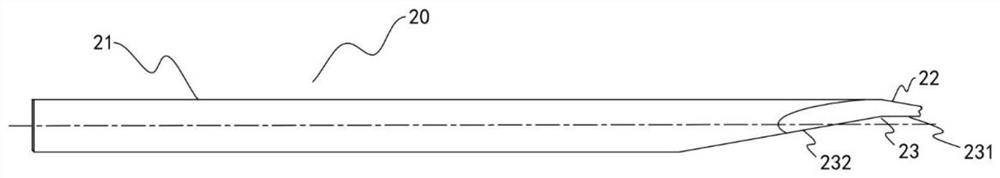
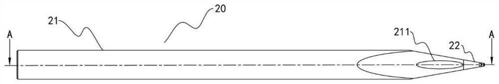
[0041] Such as Figure 2-Figure 5As shown, a deep-cavity welding capillary for welding gold strips includes a columnar capillary body 20, one end of the capillary body 20 is a gold strip guide 21, and the other end is a welding portion 22; the welding The portion 22 is in the shape of a truncated cone, its larger end face is close to the gold tape guide portion 21, and its smaller end face is away from the gold tape guide portion 21; a gap 23 is opened between the welding portion 22 and the gold tape guide portion 21, The notch 23 includes a flat cut surface 231 parallel to the axis of the riving knife main body 20 and an oblique cut surface 232 connected with the flat cut surface 231; One end is located at the smaller end surface of the welding part 22, and the other end of the flat cut surface 231 extends toward the gold strip guide part 21 and is connected with one end of the beveled cut surface 232, and the other end of the beveled cut surface 232 faces the chopper The ax...

Embodiment 2

[0043] In this embodiment, on the basis of Embodiment 1, the included angle between the chamfered surface 232 and the axis of the riving knife body 20 is 5°-15°.

Embodiment 3

[0045] In this embodiment, on the basis of Embodiment 1, the included angle between the axis where the gold band fixing hole 222 is located and the axis where the riving knife main body 20 is located is 30°-60°.


PUM


Abstract

The invention discloses a deep cavity welding chopper for welding gold strips, which comprises a columnar chopper main body, one end of the chopper main body is a gold strip guiding part, and the other end is a welding part; the welding part is in the shape of a cone The larger end surface is close to the gold ribbon guide, and the smaller end surface is away from the gold ribbon guide; there is a gap between the welding part and the gold ribbon guide, and the gap includes a flat cut surface and a The chamfered surface is connected by the cut surface; the main body of the riving knife is provided with a gold belt guide hole that penetrates the gold belt guide; the smaller end surface of the welding part is provided with a V-shaped groove, and the flat cut surface and the V-shaped groove are close to the flat surface. A gold band fixing hole for the gold band to pass through is opened between the sides of the cut surface; the gold band fixing hole is a square hole; a strip-shaped arc-shaped groove is opened on the smaller end of the welding part. The invention also discloses a production process of a deep-cavity welding chopper for welding gold strips.

Description

technical field [0001] The invention relates to the field of microelectronics, in particular to a deep cavity welding chopper for welding gold strips and a production process thereof. Background technique [0002] The traditional deep-cavity welding chopper used for micro-electronics micro-connection welding wire is easy to appear on the working surface due to the fast wire feeding when the welding wire enters the end face of the welding part from the inclined hole when the automatic wire welding machine feeds the wire. Unstable direction and severe wire swing are not conducive to fully automatic high-speed welding operations. Therefore, if the original deep cavity welding chopper is to be used for gold ribbon welding machines to feed gold ribbons, its structure needs to be improved. Contents of the invention [0003] In order to solve the problems in the prior art, the invention provides a deep-cavity welding chopper for welding gold strips and a production process thereo...

Claims


Application Information

Patent Timeline
Patent Type & Authority Patents(China)
IPC IPC(8): B23P15/28
CPCB23P15/28
Inventor 杨强
Owner 无锡精蓉创材料科技有限公司
Why Eureka
Try Eureka