
Device for fastening a finishing strip

a technology for finishing strips and devices, which is applied in the direction of construction, building construction, etc., can solve the problems of insufficient clamping connection between the receptacle web and the finishing strip, and achieve the effects of enhancing the withdrawal resistance, and reducing the bending length of the spring tongu

Inactive Publication Date: 2019-12-19
NEUHOFER FRANZ
View PDF6 Cites 0 Cited by
  • Summary
  • Abstract
  • Description
  • Claims
  • Application Information

AI Technical Summary

Benefits of technology

The patent text describes a mount and finishing strip connection design that provides a secure and flexible clamping connection. The spring tongues have a unique profile that allows for a nonlinear wall profile to linear finishing strips without compromising the clamping effect. The catch ribs on the spring tongues enhance the withdrawal resistance between the mount and finishing strip. Additionally, the spring tongues cross each other to form additional catch supports, improving the overall connection. This design allows for an advantageous spring travel and compensation between nonlinear walls and linear wall finishing strips.

Problems solved by technology

Since a wall profile which is not linear has to be expected, difficulties result during the plugging of the finishing strip onto the receptacle web of the mounting profile.
This is because longer sections of the finishing strips require greater play in the case of a nonlinear wall profile in relation to the engagement of the receptacle web in the receptacle groove of the finishing strip provided for this purpose, to be able to plug the finishing strip onto the mounting profile, while with shorter sections of the finishing strip, a sufficient clamping connection between the receptacle web and the finishing strip is endangered by such play.

Method used


Image

  • Device for fastening a finishing strip
  • Device for fastening a finishing strip
  • Device for fastening a finishing strip

Examples


Embodiment Construction

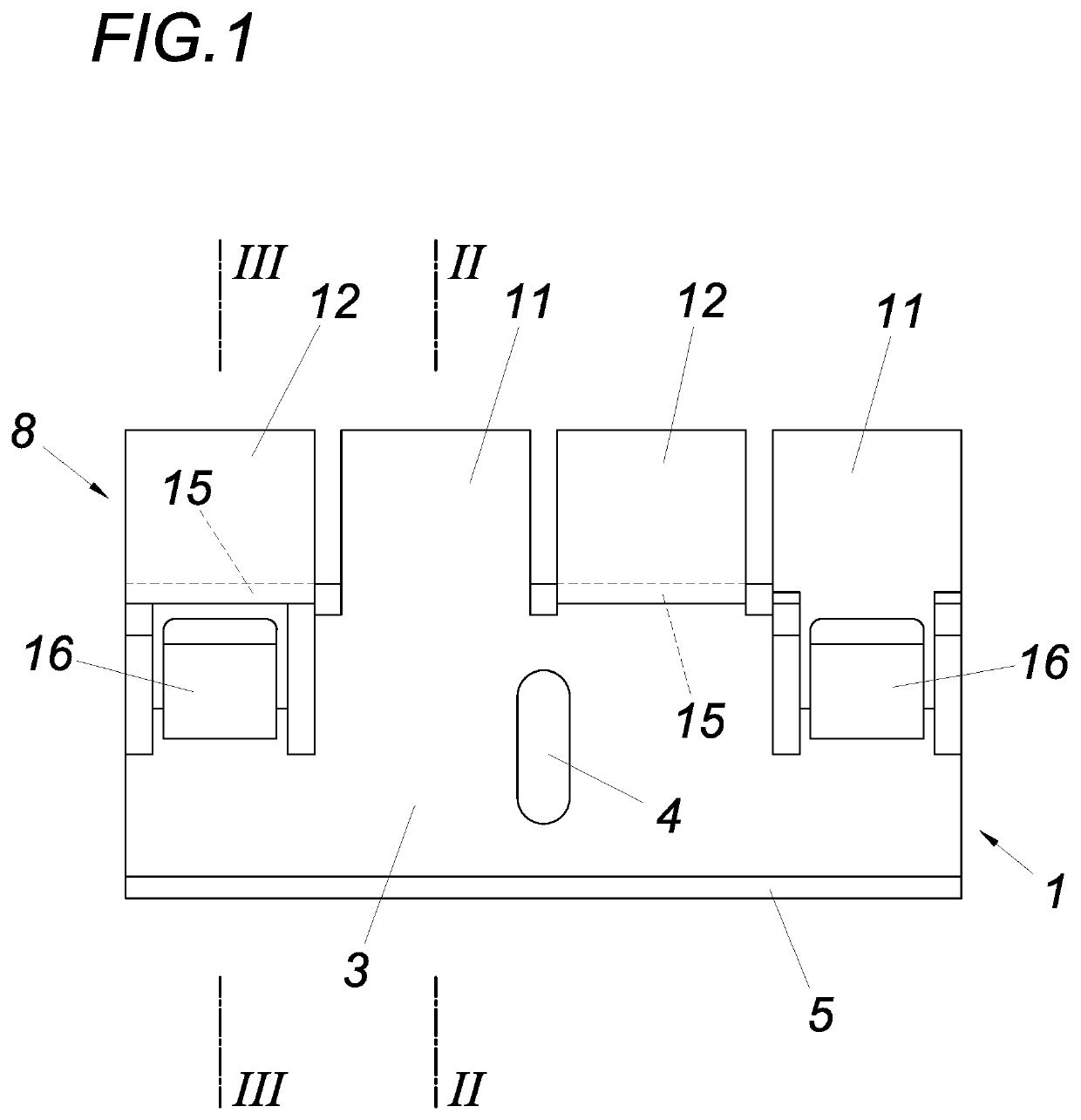
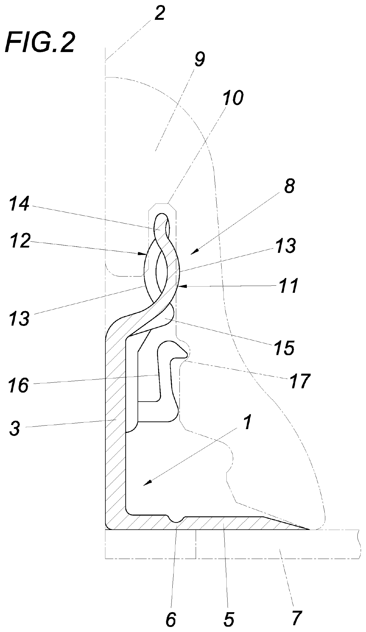
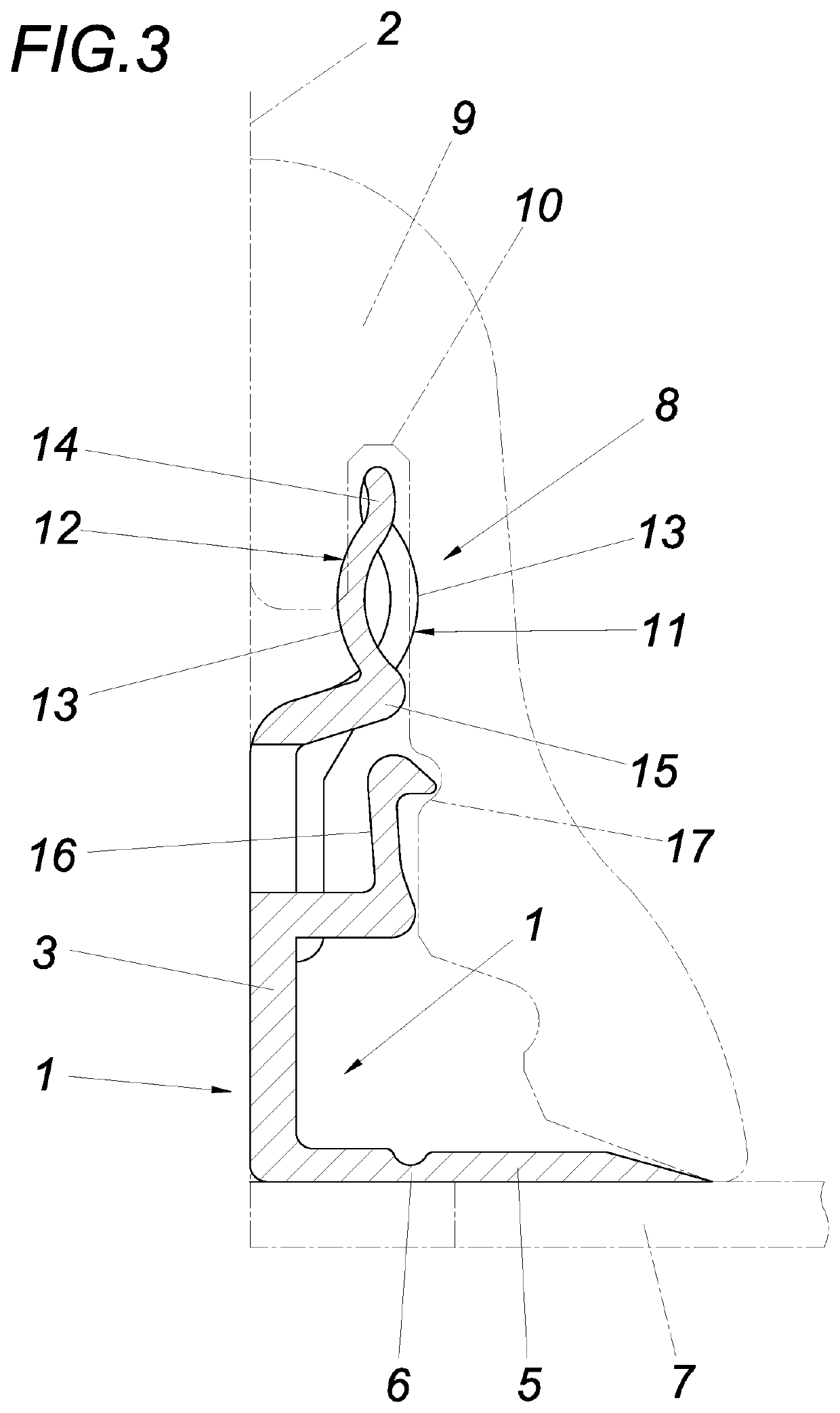
[0014]The device according to the invention has a mount 1, for example, made of plastic, which forms a wall leg 3 fastenable on a wall 2, which is provided with at least one oblong hole 4 for a fastening screw. The wall leg 3 protrudes from a base leg 5, which is connected via an intended breakpoint 6 to the wall leg 3 and can be separated from the wall leg 3 if needed. With the aid of the base leg 5, the mount 1 can be supported on a floor covering 7. In the upper edge region, the wall leg 3 forms a receptacle web 8 for the finishing strip 9 to be fastened on the wall 2, which has a receptacle groove 10 open on top for the receptacle groove 7 for this purpose. The receptacle web 8, which is offset away from the wall 2 in relation to the wall leg 3, and which extends approximately parallel to the wall 2 or the wall leg 3, respectively, is composed of at least three, in the exemplary embodiment of four spring tongues 11 and 12 arrayed adjacent in the web longitudinal direction, which...


PUM


Abstract

A device for fastening a finishing strip (9) is described, comprising a mount (1), which forms a wall leg (3), and which has a downwardly protruding receptacle web (8) for the clamped holding of the finishing strip (9), which receptacle web (8) is offset transversely in relation to the wall leg (3) and engages in a receptacle groove (10) of the finishing strip (9), which receptacle groove (10) is open on the bottom. To provide advantageous construction conditions, it is proposed that the receptacle web (8) comprises at least three spring tongues (11, 12), which are arrayed adjacent in the web longitudinal direction and protrude upward freely, and which are bulged alternately concavely and convexly in relation to the wall leg (3) about axes parallel to the web.

Description

FIELD OF THE INVENTION[0001]The invention relates to a device for fastening a finishing strip comprising a mount, which forms a wall leg, and which has an upwardly protruding receptacle web offset transversely in relation to the wall leg which engages in a receptacle groove open on the bottom of the finishing strip for the clamping accommodation of the finishing strip.DESCRIPTION OF THE PRIOR ART[0002]For fastening finishing strips for floors, providing a mount made of a plastic profile is known (EP 2 169 143 A2), which has a wall leg fastenable on the wall and a receptacle web for the finishing strip, which is plugged onto the wall-parallel receptacle web, which is offset transversely in relation to the wall leg and is approximately parallel to the wall. The receptacle web engages in this case in a receptacle groove of the finishing strip, which is fixed with the aid of clamping ribs provided on the receptacle web. Since a wall profile which is not linear has to be expected, diffic...

Claims


Application Information

Patent Timeline
Patent Type & Authority Applications(United States)
IPC IPC(8): E04F19/04
CPCE04F19/0468
Inventor NEUHOFER, FRANZ
Owner NEUHOFER FRANZ
Learn More