Power tool

A power tool and working head technology, which is applied in the field of hand-held power tools, can solve the problems of large operating force and difficulty of the wrench

Active Publication Date: 2015-06-10
POSITEC POWER TOOLS (SUZHOU) CO LTD
View PDF6 Cites 6 Cited by
  • Summary
  • Abstract
  • Description
  • Claims
  • Application Information

AI Technical Summary

Problems solved by technology

When removing accessories such as knives, the wrench needs a large operating force to move, which is difficult fo

Method used


Image

  • Power tool
  • Power tool
  • Power tool

Examples


Embodiment 1

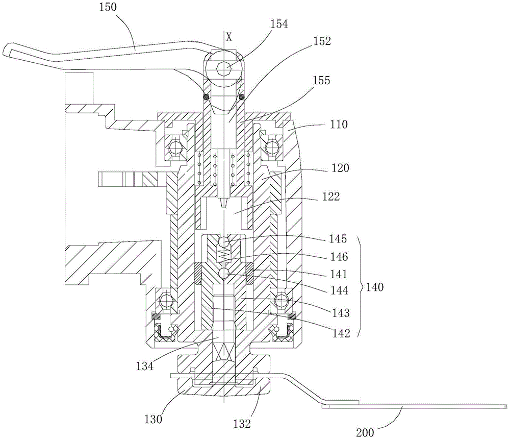
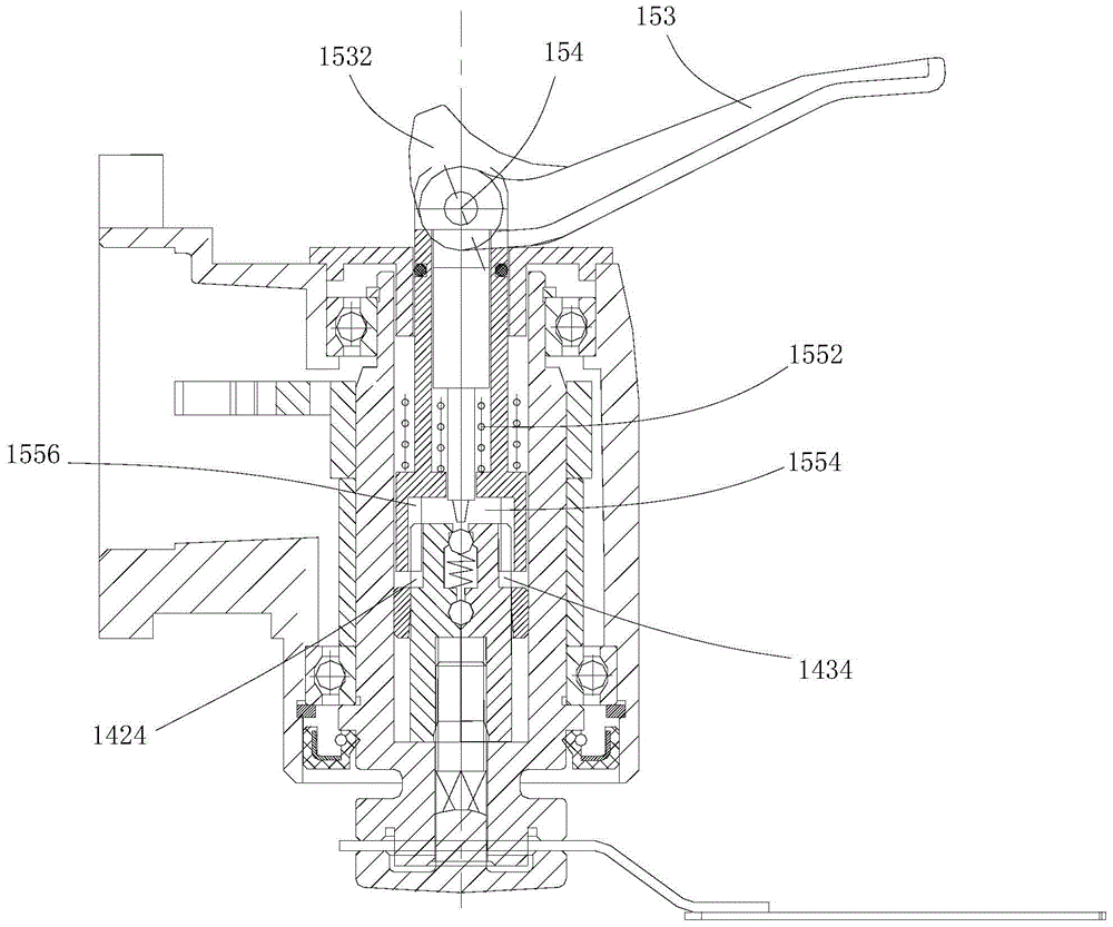
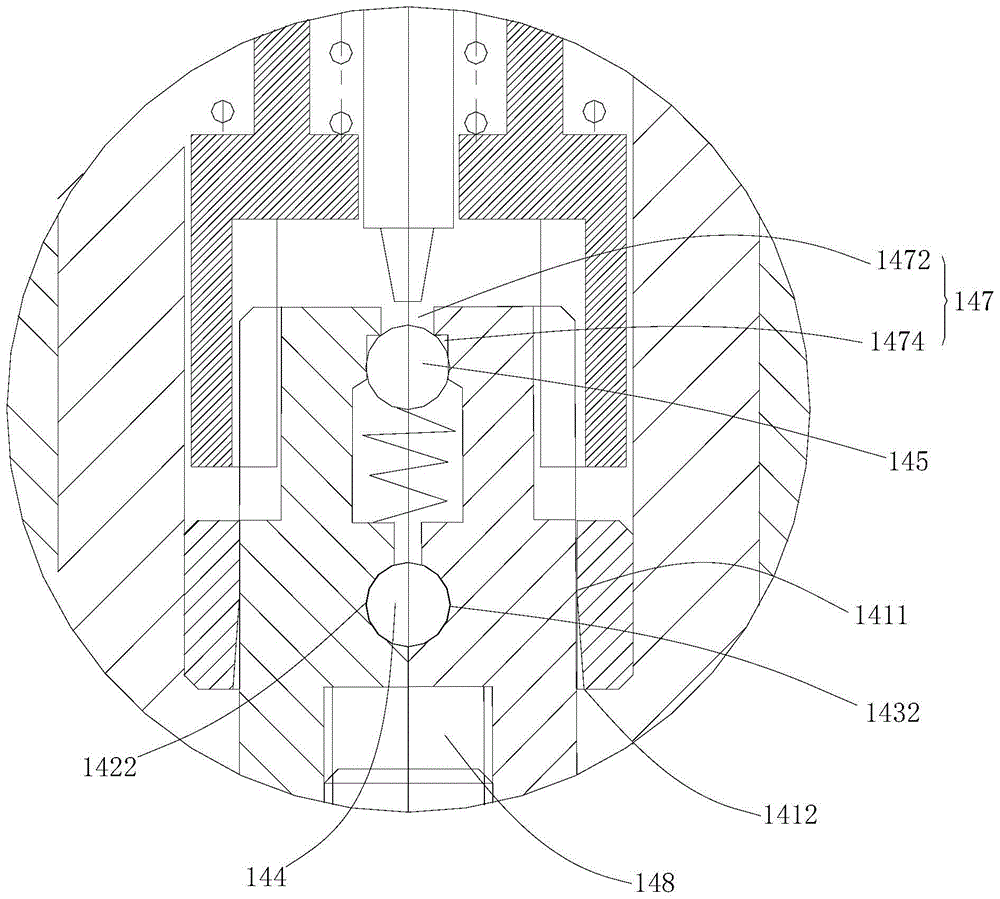
[0051] Please refer to Figure 1 to Figure 9 , the power tool of Embodiment 1, which is described here by taking a multifunctional machine as an example, includes a housing 110, an output shaft 120 disposed in the housing 110 and one end extending out of the housing 110, a fixing member 130, and an output shaft 120 disposed on the output shaft 120. The locking assembly 140 and the driving mechanism 150 in the. The output shaft 120 is used to drive the working head 200 to work, wherein the output shaft 120 can swing around its own axis X, which is well known to those skilled in the art and is not the focus of this embodiment, so it will not be described again. The fixing part 130 is used to press the working head 200 onto the free end of the output shaft 120 . The locking assembly 140 is used to lock the fixing member 130 to fix the working head 200 on the output shaft 120 . The driving mechanism 150 is used to drive the locking assembly 140 to move to achieve or release the ...

Embodiment 2

[0076] The power tool of the second embodiment of the present invention is similar in structure to the first embodiment, the only difference is the locking component, so only the locking component will be described below.

[0077] Please refer to Figure 10 and Figure 11 , the locking assembly 740 of the power tool in the second embodiment includes a sleeve 741, a first clamping piece 742, and a second clamping piece 743, and the rotation between the first clamping piece 742 and the second clamping piece 743 The shaft 744 , the locking piece 745 , and the first elastic piece 746 .

[0078] In this embodiment, the locking member 745 is a cross, including a blocking portion 7452 abutting against the first clamping component 742 and the second clamping component 743 and a pressing portion 7454 extending out of the channel 747 . Certainly, the pressing portion 7454 may not protrude from the channel 747 , and when the locking member 745 needs to be moved, the push rod can be ins...


PUM


Abstract

The invention relates to a power tool which comprises a shell, an output shaft, a fixing member for pressing a working head onto the output shaft, a locking assembly for locking the fixing member and a driving mechanism, wherein the locking assembly comprises a sleeve fixed in the output shaft, a first clamping member and a second clamping member contained in the sleeve, as well as a rotation shaft arranged between the first clamping member and the second clamping member; the first clamping member and the second clamping member can rotate by taking the rotation shaft as the center, so that the locking assembly is located at a locking position or a release position; a locking member for keeping the locking assembly at the locking position and a first elastic member for elastically supporting the locking member are further arranged between the first clamping member and the second clamping member; the driving mechanism comprises a push rod which is arranged in the output shaft and can move along the output shaft axially; the push rod can push the locking member to move when movement, so as to release restriction on the locking assembly. With adoption of the power tool, the detachment process can be completed conveniently through simple pressing action, without rotating a wrench for multiple turns; the starting force is small.

Description

technical field [0001] The invention relates to a power tool, in particular to a hand-held power tool. Background technique [0002] The multi-function machine is a common oscillating power tool in the industry, and its working method is that its output shaft makes oscillating motion around the axis. Therefore, when different accessory working heads are installed on the output shaft, different operating functions can be realized, such as sawing, cutting, grinding, scraping, etc., to meet different working requirements. [0003] In the structure of the replacement of the accessories of the traditional multi-function machine, most of them use the pressure plate screw and the integral inner nut to fix it with threads. When removing accessories such as knives, the wrench needs a large operating force to move, which is difficult for manual operation, and it needs to be rotated enough times to loosen the pressure plate screw during disassembly. Contents of the invention [000...

Claims


Application Information

Patent Timeline
IPC IPC(8): B25F3/00B25F5/00
CPCB25F3/00B25F5/001
Inventor 顾华吴海全李辉
Owner POSITEC POWER TOOLS (SUZHOU) CO LTD
Why Eureka
Try Eureka