Waterproof and dustproof device for electronic seal lock

An electronic seal lock, waterproof and dustproof technology, applied in the field of machinery, can solve the problems of normal work, muddy water, difficult to guarantee complete and lasting protection, etc., to achieve reliable waterproof and dustproof, prolong service life, and ensure reliable operation. Effect

Inactive Publication Date: 2017-04-05
SHANGHAI INST OF TECH
View PDF5 Cites 2 Cited by
  • Summary
  • Abstract
  • Description
  • Claims
  • Application Information

AI Technical Summary

Problems solved by technology

[0003] However, due to the limitation of the size of the electronic seal lock and the power supply capacity, etc., for the electronic seal lock with a lock beam and a deadbolt structure and a long-term reusable electronic seal lock, generally there is no reliable seal at the bolt hole, even if the printed circuit The boards are generally coated with protective paint, but complete and lasting protection is difficult to guarantee, and the protection of moving parts is even more difficult to achieve, especially the electronic seal lock is hung on the door handle and handle bracket of the freight container for a long time, and it is subjected to shock and vibration. It is also often in harsh environments such as strong sunlight, violent wind and rain, or muddy water. Therefore, among many existing electronic seal locks, after a period of normal use, there are suddenly a variety of malfunctions during operation. Analyzing the causes of electromechanical failures, most of them are caused by the intrusion of dust, water or moisture, which makes the surface of the micro-motor and its transmission parts, especially the electronic devices and their solder joints moldy and rusty.

Method used


Image

  • Waterproof and dustproof device for electronic seal lock
  • Waterproof and dustproof device for electronic seal lock
  • Waterproof and dustproof device for electronic seal lock

Examples


Embodiment Construction

[0028] In order to make it easy to understand the technical means, creation features, achieved goals and effects of the present invention, the present invention will be further described below with reference to specific drawings.

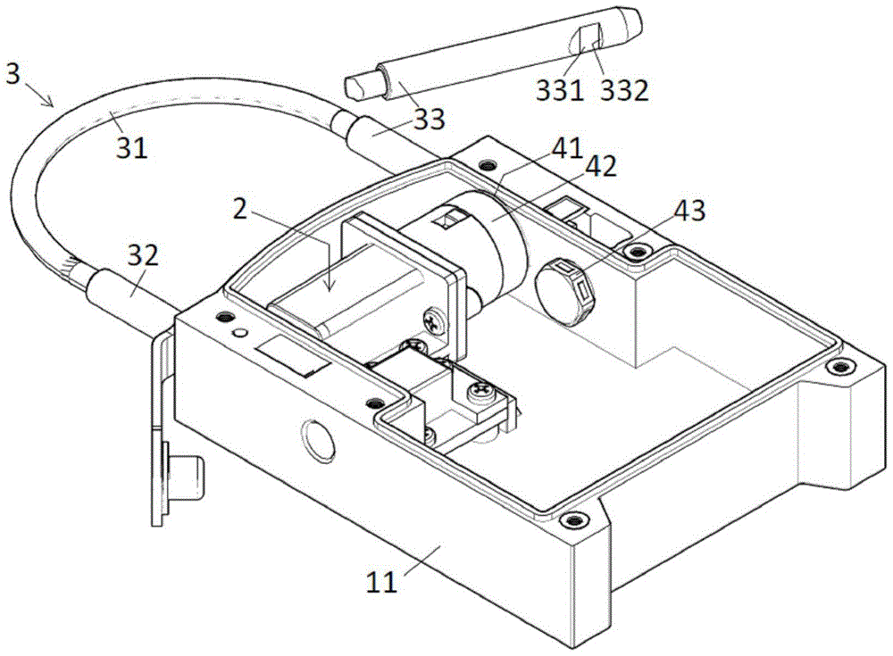
[0029] refer to figure 1 , a waterproof and dustproof device for an electronic seal lock, comprising a lock shell 11, a drive mechanism 2, a locking mechanism 3, a lock tongue hole sealing device composed of a circular silicone rubber seal 41 and a pressing sleeve 42, and a waterproof and breathable device 43.

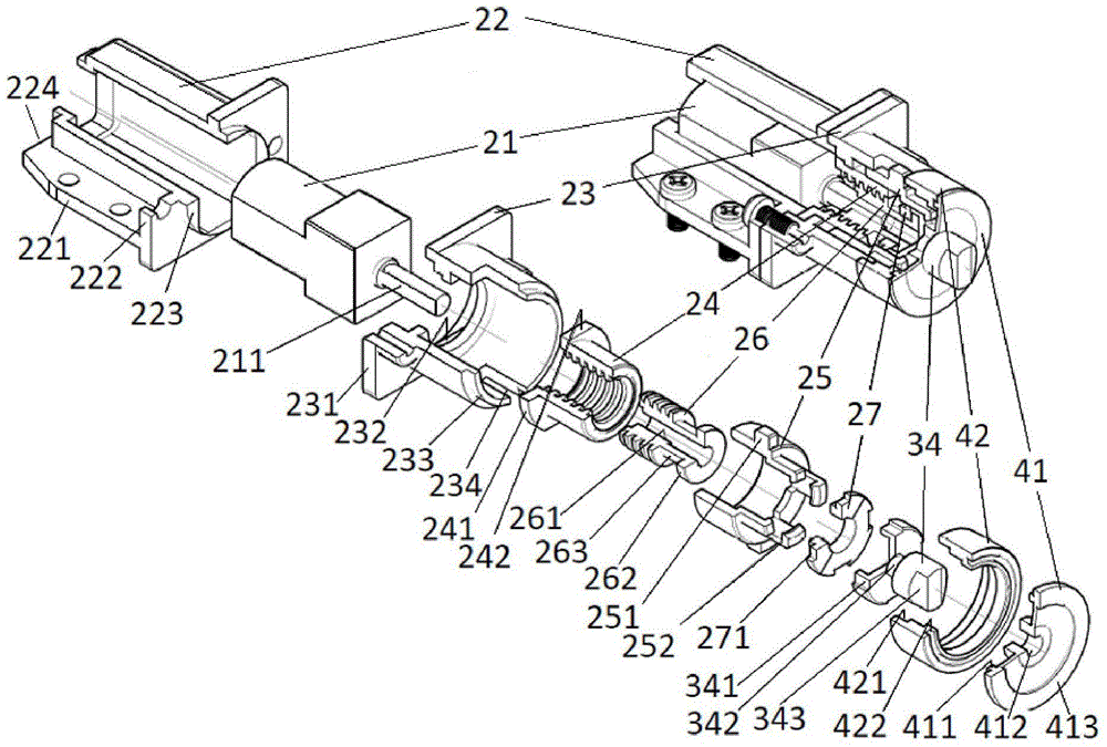
[0030] refer to figure 2 , The drive mechanism 2 is composed of a gear reduction motor 21, a motor base 22, a screw nut transmission pair 26 and 24, a guide sleeve 23, a sliding sleeve 25 and a Huff washer 27.

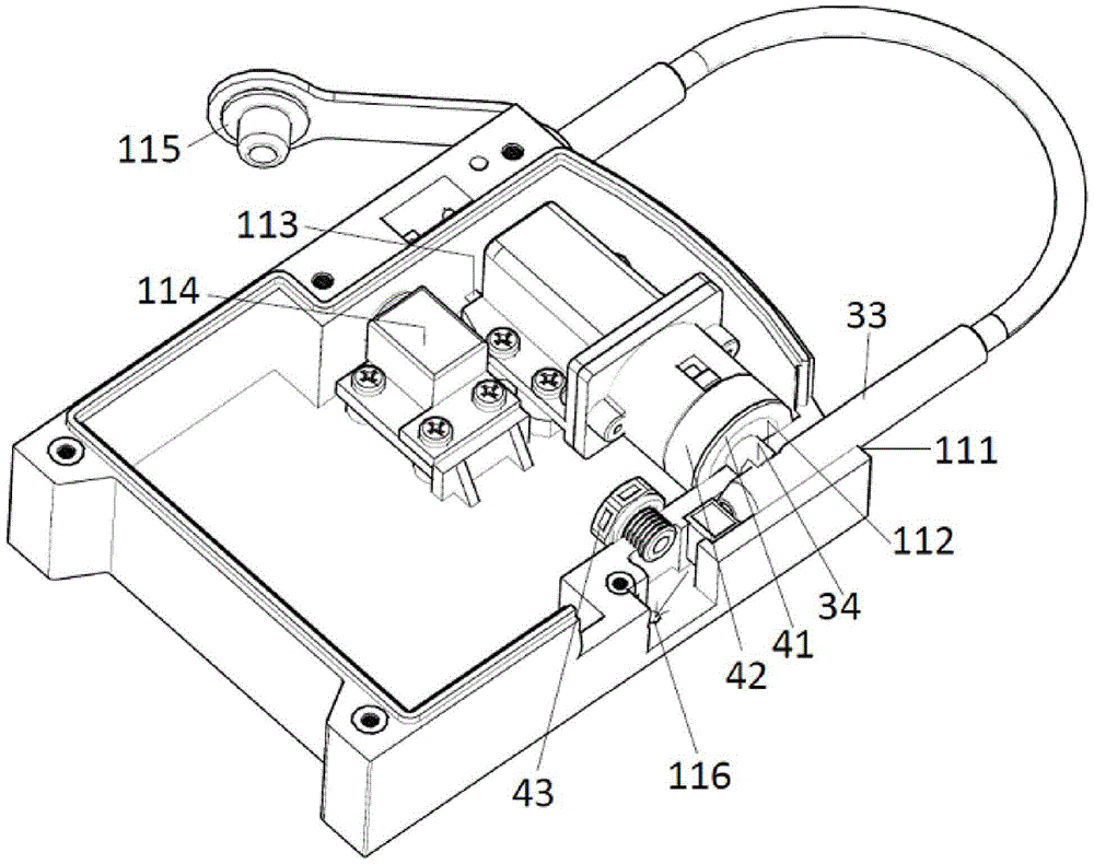
[0031] refer to image 3 , the lock shell 11 is provided with a vertical intersecting lock beam socket 111 and a lock tongue hole 112, the lock shell bottom plate at the rear of the drive mechanism 2 has a limit step 113 that wit...


PUM


Abstract

The invention relates to the field of machines, in particular to locksets, and particularly provides a waterproof and dustproof device for an electronic seal lock. The waterproof and dustproof device comprises a lock shell, a driving mechanism, a locking mechanism, a lock tongue hole sealing device and a waterproof ventilation valve, wherein a lock beam inserting hole and a lock tongue hole are formed in the lock shell, and perpendicular to each other; the driving mechanism is mounted in an inner cavity in the lock shell, and comprises a gear reducer motor, a motor seat, a lead screw nut transmission pair, a guiding sleeve, a sliding sleeve and a half spacer; the locking mechanism comprises a steel wire rope lock beam and a lock tongue; a central hole in a circular silicone rubber sealing component of the lock tongue hole sealing device is closely connected with a groove in the lock tongue; the circumferential area is in fit with the inner circumferential wall of the lock tongue hole and is pressed by a gland. By adopting the technical scheme, the waterproof and dustproof device has the advantages that the electronic seal lock can be completely and reliably sealed at the lock tongue and in the lock tongue hole, so that the balance among the air pressure, the humidity and the temperature of the inner cavity in the electronic seal lock can be maintained, the running of a product can be reliable, and the service life of the product can be prolonged.

Description

technical field [0001] The invention relates to the field of machinery, in particular to a lock, and in particular to a waterproof and dustproof device for an electronic seal lock. Background technique [0002] The safety management of goods in transit is undoubtedly an important link in the modern management of the logistics industry. In order to prevent theft and exchange of goods in transit, it is necessary to prevent the unauthorised opening of the freight container while the goods are in transit. Traditional security measures mostly use disposable plastic seals or lead seals, which are easy to be imitated, easy to be illegally replaced, difficult to distinguish between true and false, and inability to immediately find problems, such as low security. At present, a variety of electronic seal locks containing modern electronic technology have gradually been widely used in the modern logistics industry. They not only have the functions of traditional plastic seals and lead...

Claims


Application Information

Patent Timeline
Patent Type & Authority Patents(China)
IPC IPC(8): E05B39/00E05B47/00E05B67/38
Inventor 林伟丁志刚王毅男岳璐璐沈宇星
Owner SHANGHAI INST OF TECH
Why Eureka
Try Eureka