

Air pipe type indoor air conditioner and control method thereof
An indoor unit and air duct type technology of an air conditioner, which is applied in heating and ventilation control systems, air conditioning systems, air flow control components, etc. Sensation and other issues, to achieve the effect of optimal comfort
- Summary
- Abstract
- Description
- Claims
- Application Information
AI Technical Summary
Problems solved by technology
Method used
Image

Examples
Embodiment 1
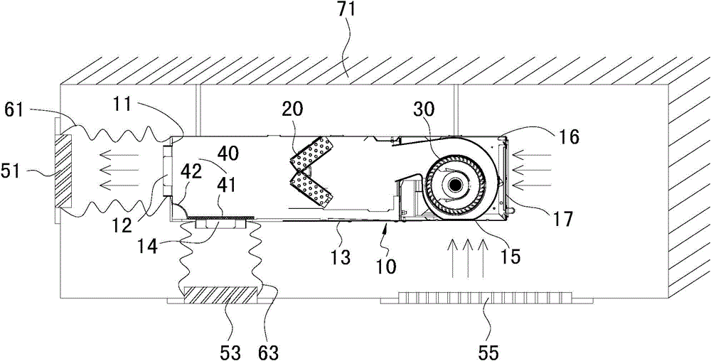
[0035] Figure 1a , 1bIt is a sectional view of the indoor unit of the ducted air conditioner in Embodiment 1 of the present invention. As shown in the figure, the indoor unit of the ducted air conditioner in this embodiment includes: a housing 10, an indoor heat exchanger 20, an indoor fan 30 and an opening and closing mechanism 40, wherein the housing 10 is provided with an air return port . The front air outlet 12 and the lower air outlet 14, the front air outlet 12 is arranged on the front side wall 11 of the housing, and the lower air outlet 14 is arranged on the front part of the lower side wall 13 of the housing. Preferably, there are two air return ports, including a lower air return port 15 disposed on the rear portion of the lower side wall 13 of the housing and a rear air return port 17 disposed on the rear side wall 16 of the housing. The indoor heat exchanger 20 is arranged in the housing 10 and is located between the air return port and the front air outlet 12 a...
Embodiment 2
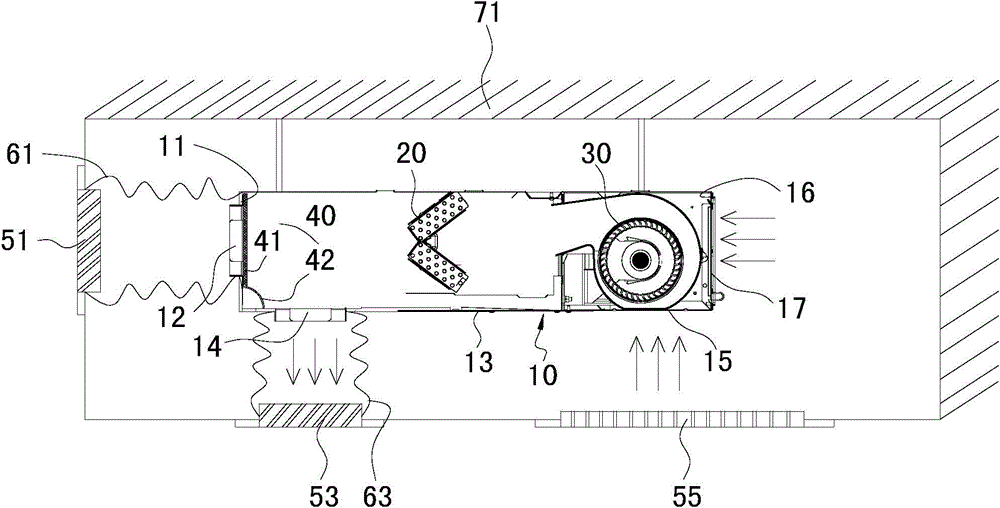
[0040] Such as figure 2 As shown, the structure of the indoor unit of the ducted air conditioner in this embodiment is generally the same as that in Embodiment 1, except that the indoor heat exchanger 20 is located on the suction side of the indoor fan 30 .
Embodiment 3
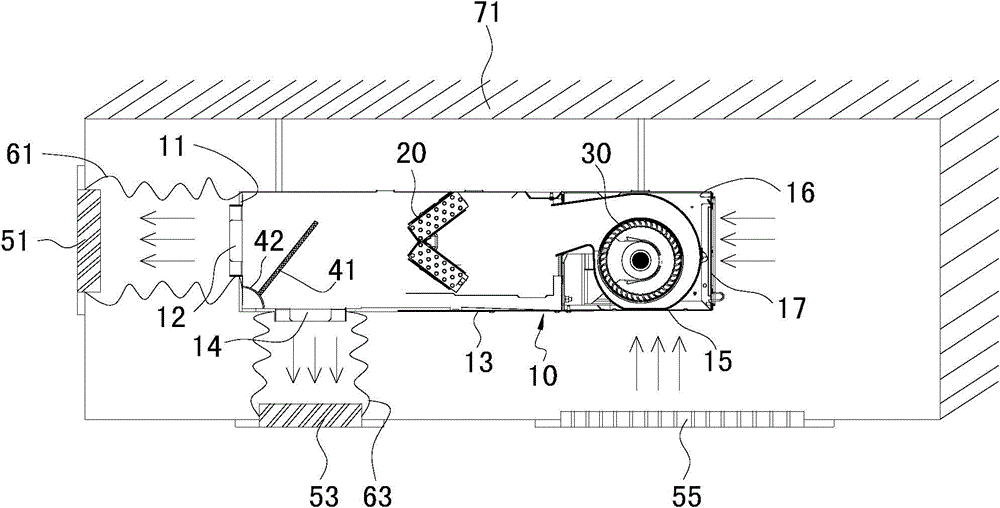
[0042] Such as image 3 As shown, the structure of the indoor unit of the ducted air conditioner in this embodiment is generally the same as that in Embodiment 1, the difference is that the cross-sectional shape of the indoor heat exchanger 20 is in the shape of a "one", and the indoor The heat exchanger 20 is inclined at a certain angle with the axial direction of the housing 10 .
PUM
 Abstract
Description
Claims
Application Information