
Rapid battery detection device and rapid battery detection system

A detection device and detection system technology, applied in the direction of measurement device, measurement of electricity, measurement of electric variables, etc., can solve the problems of many output points, cluttered circuit layout, mutual interference between slide rails and probes, etc., to reduce costs and reduce distribution. And control the number of output points, the effect of the stability of the test method

Inactive Publication Date: 2015-06-10
苏州大源自动化科技股份有限公司
View PDF7 Cites 9 Cited by
  • Summary
  • Abstract
  • Description
  • Claims
  • Application Information

AI Technical Summary

Problems solved by technology

After the battery production is completed, it is necessary to carry out product testing on the battery to test performance parameters such as voltage, current, and internal resistance of the battery. In the prior art, by placing the battery to be tested in the battery box, and then testing The positive and negative poles are connected to the probe respectively, one end of the probe is connected to the positive or negative pole of the battery, and the other end is connected to the tester through a wire. Complete the test of multiple batteries to be tested. In the existing technology, since the positive and negative poles of each battery need to be connected to the battery detection device through wires, there are many control output points, which increases the cost and the wiring layout is messy. , and during the test, a single battery is used to detect sequentially, so the control needs to be complicated and the stability is low
[0003] In addition, in the prior art, when testing, the box body is placed on the slide rail, the battery is generally placed forward, and the bottom surface is in contact with the slide rail, but the bottom surface of the box body needs to open a through hole to connect with the probe, so Setting, in specific use, it is easy to cause mutual interference between the slide rail and the probe, and the overall structure is complex

Method used


Image

  • Rapid battery detection device and rapid battery detection system
  • Rapid battery detection device and rapid battery detection system
  • Rapid battery detection device and rapid battery detection system

Examples


Embodiment Construction

[0025] The specific implementation manners of the present invention will be further described in detail below in conjunction with the accompanying drawings and embodiments. The following examples are used to illustrate the present invention, but are not intended to limit the scope of the present invention.

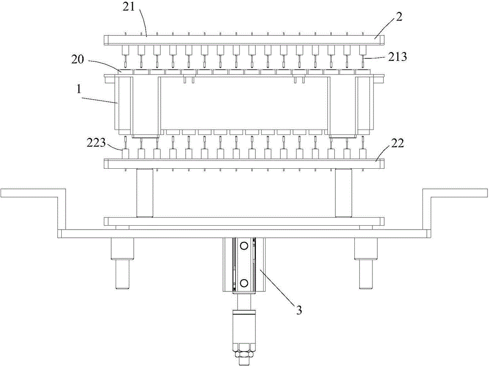
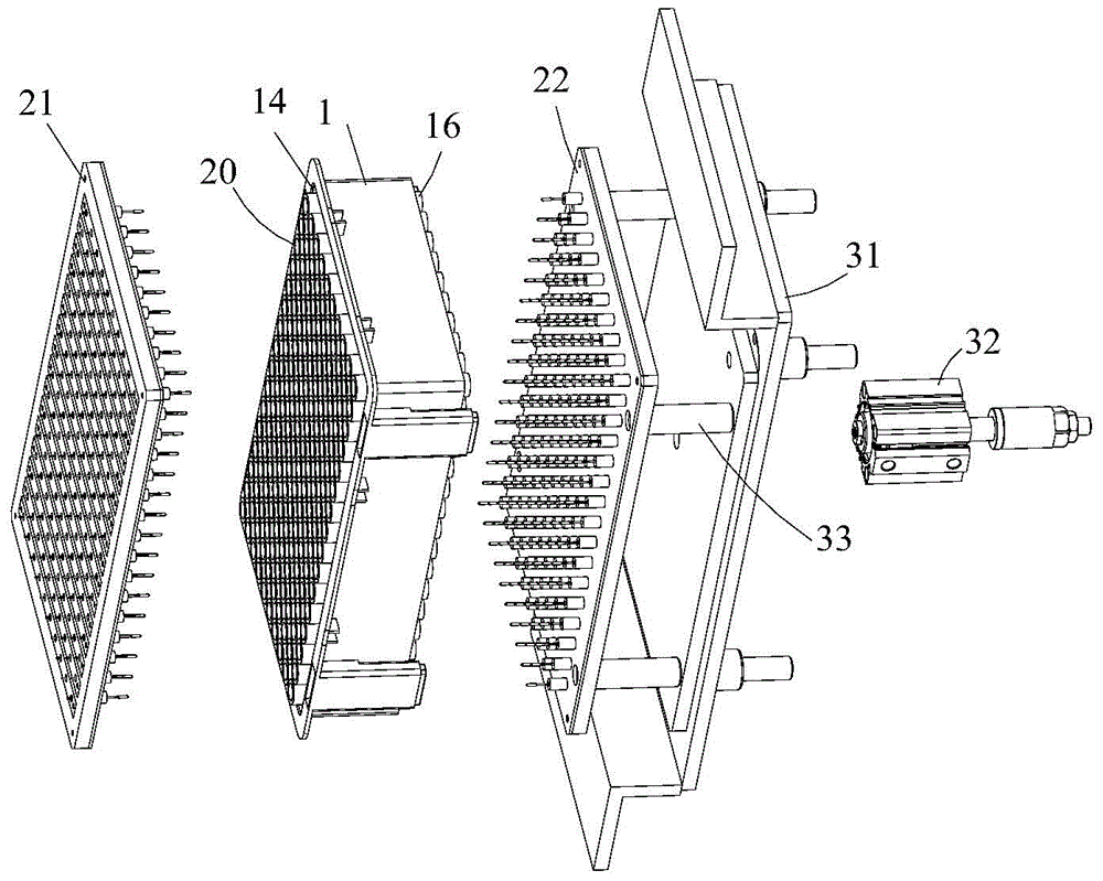
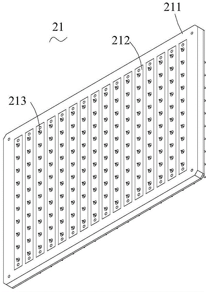
[0026] see Figure 1 to Figure 6 , a battery rapid detection device described in a preferred embodiment of the present invention includes a box body 1 for installing a plurality of batteries to be tested 20, a detection piece 2 for detecting the battery to be tested 20, and a probe for fixing the detection piece 2 Mobile mechanism3. In this embodiment, 160 batteries to be tested 20 can be installed in one box body 1, each of the batteries to be tested 20 has a positive pole (unlabeled) and a negative pole (unlabeled), and the box body 1 has oppositely arranged The first side 11 and the second side 12 and the bottom surface 13 connecting the first side 11 and the second s...


PUM


Abstract

The invention relates to a rapid battery detection device and a rapid battery detection system. The rapid battery detection device comprises a box for installing a plurality of batteries to be tested, and a detection element for detecting the batteries to be tested. The box comprises a first lateral side and a second lateral side that are opposite to each other. The box is provided with an accommodating chamber which is formed by recessing from the first lateral side toward the second lateral side and is used for accommodating the batteries to be tested; and the box is provided with a plurality of through holes running through from the second lateral side toward the accommodating chamber. The detection element comprises a first testing plate outside the second lateral side and a second testing plate outside the second lateral side. On the first lateral side, the plurality of batteries to be tested that are installed inside the accommodating chamber is divided into n parallel lines; and the first testing plate is provided with n first testing strips corresponding to the n lines. On the second lateral side, the plurality of batteries to be tested that are installed inside the accommodating chamber is divided into m parallel lines; and the second testing plate is provided with m section testing strips corresponding to the m lines. The direction of the first testing strips is different from the direction of the second testing strips.

Description

technical field [0001] The invention relates to a battery rapid detection device and a battery rapid detection system. Background technique [0002] Battery (Battery) refers to a cup, tank or other container or part of a composite container that contains an electrolyte solution and a metal electrode to generate current. It is a device that can convert chemical energy into electrical energy. It has a positive pole and a negative pole. After the battery production is completed, it is necessary to carry out product testing on the battery to test performance parameters such as voltage, current, and internal resistance of the battery. In the prior art, by placing the battery to be tested in the battery box, and then testing The positive and negative poles are connected to the probe respectively, one end of the probe is connected to the positive or negative pole of the battery, and the other end is connected to the tester through a wire. Complete the test of multiple batteries to...

Claims


Application Information

Patent Timeline
Patent Type & Authority Applications(China)
IPC IPC(8): G01R31/36
Inventor 周跃进夏建春
Owner 苏州大源自动化科技股份有限公司
Learn More