Touch display panel, manufacturing method thereof and touch display device
A technology for a touch display panel and a manufacturing method, which are applied in the fields of optics, instruments, electrical and digital data processing, etc., can solve the problems of low pressure resistance of the touch display panel.
- Summary
- Abstract
- Description
- Claims
- Application Information
AI Technical Summary
Problems solved by technology
Method used
Image
Examples
Embodiment 1
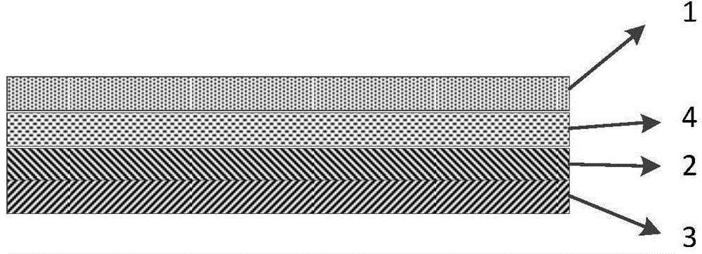
[0032] figure 1 A schematic structural diagram of the touch display panel provided by the first embodiment is shown, as shown in figure 1 As shown, the touch display panel provided in the first embodiment includes a touch substrate 1, a first display substrate 2, and a second display substrate 3 arranged in sequence, and the gap between the first display substrate 2 and the touch substrate 1 is An elastic buffer layer 4 is provided.
[0033] Specifically, the elastic buffer layer 4 can be disposed on the first display substrate 2 or on the touch control substrate 1 .
[0034] In the touch display panel described in this embodiment, an elastic buffer layer is provided between the touch substrate and the first display substrate, so that when the touch display panel is pressed by an external force, the external force will first make the elastic buffer layer close to the touch substrate layer is compressed, the elastic buffer layer deforms under the action of external force, so ...
Embodiment 2
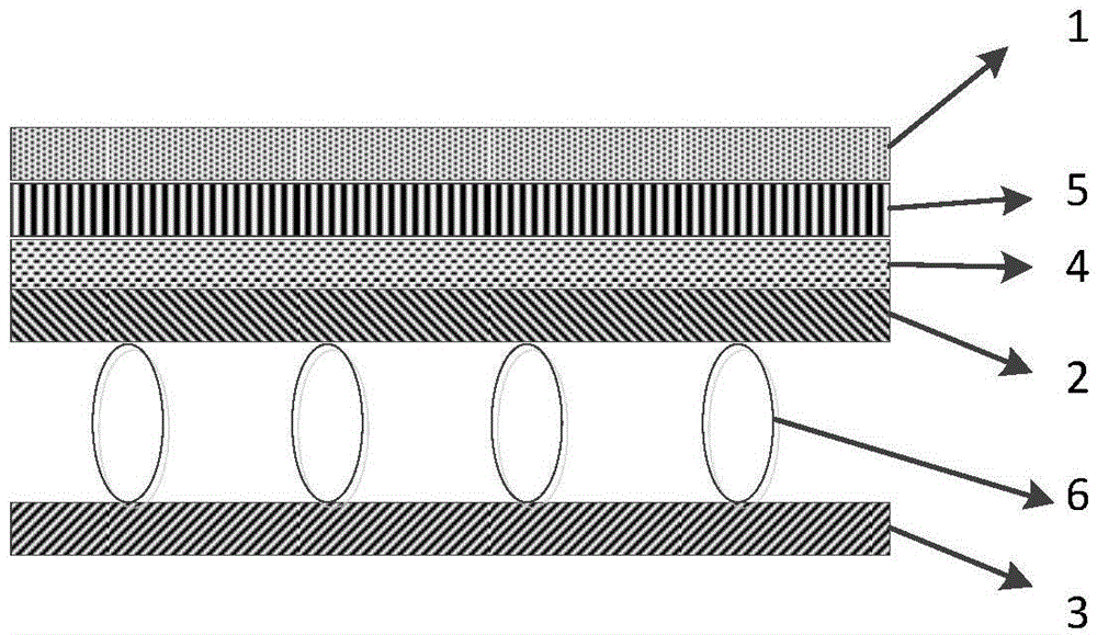
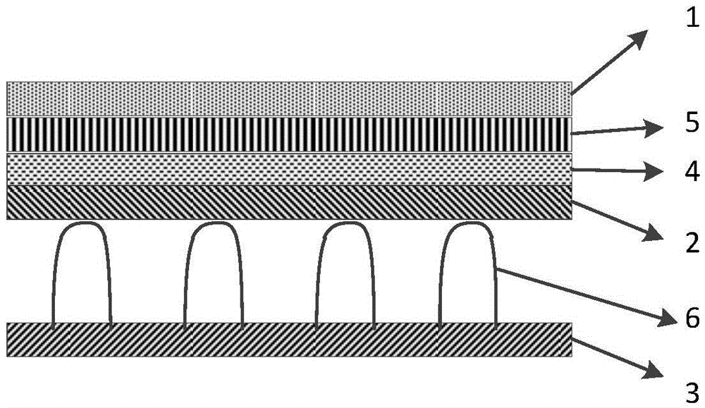
[0036] see figure 2 , 3 4. The second embodiment provides a touch display panel. The touch display panel provided in this embodiment includes a touch substrate 1, a first display substrate 2 and a second display substrate 3 arranged in sequence. The first display substrate 3 An elastic buffer layer 4 is disposed between a display substrate 2 and the touch substrate 1 . Wherein, the elastic buffer layer 4 is disposed on the first display substrate 1 . An optically transparent adhesive layer 5 (OCA) or an optically transparent resin layer (OCR) is disposed between the touch control substrate 1 and the elastic buffer layer 4 . The elastic buffer layer 4 is bonded to the touch substrate 1 by optically transparent glue or optically transparent resin.
[0037] Preferably, a spacer 6 is provided between the first display substrate 2 and the second display substrate 3 , and the material of the elastic buffer layer 4 is the same as that of the spacer 6 .
[0038] The spacer 6 is a...
Embodiment 3
[0048]Embodiment 3 provides a touch display device, including the touch display panel described in Embodiment 1 or 2 above.
[0049] Since the touch display device provided by the present invention includes the touch display panel described in the first or second embodiment above, the touch display device also has good pressure resistance.
[0050] Wherein, the touch display device described in this embodiment can be applied in display devices such as mobile phones, tablet computers, video cameras, cameras, televisions, and printers.
PUM
 Abstract
Description
Claims
Application Information
 - R&D
- Intellectual Property
- Life Sciences
- Materials
- Tech Scout
- Unparalleled Data Quality
- Higher Quality Content
- 60% Fewer Hallucinations
Browse by: Latest US Patents, China's latest patents, Technical Efficacy Thesaurus, Application Domain, Technology Topic, Popular Technical Reports.
© 2025 PatSnap. All rights reserved.Legal|Privacy policy|Modern Slavery Act Transparency Statement|Sitemap|About US| Contact US: help@patsnap.com


