Pipe linear cutting tool

A wire-cut tooling and pipe technology, applied in the direction of attachments, manufacturing tools, electric processing equipment, etc., can solve the problems of low clamping efficiency and inconvenient operation of wire-cut tooling, and achieve improved production efficiency, convenient clamping operation, Avoid the sloshing effect

Inactive Publication Date: 2015-06-17
LIUZHOU YONGYI MACHINERY MFG
View PDF6 Cites 4 Cited by
  • Summary
  • Abstract
  • Description
  • Claims
  • Application Information

AI Technical Summary

Problems solved by technology

[0003] The purpose of the present invention is to provide a pipe wire cutting tool, which can solve the problems of inconvenient operation and low clamping efficiency of the wire cutting tool

Method used


Image

  • Pipe linear cutting tool
  • Pipe linear cutting tool

Examples


Embodiment Construction

[0019] The present invention will be described in further detail below in conjunction with accompanying drawing embodiment:

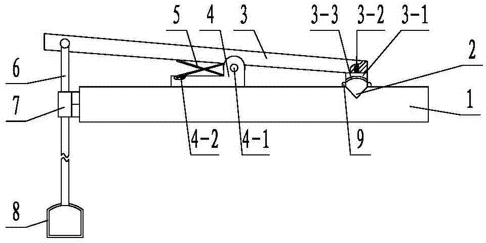
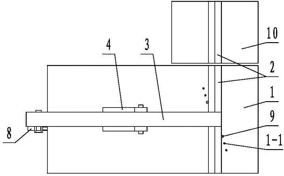
[0020] figure 1 and figure 2 The pipe wire cutting tool shown mainly includes a support plate 10, a base plate 1, a pressure bar 3, a support 4, a cross bar 4-1, a torsion spring 5, a boom 6 and a pedal 8, and the support plate 10 and the base plate 1 are horizontally spaced Setting, the base plate 1 and the support plate 10 are provided with a V-shaped groove 2 for placing pipes, the bottom of the V-shaped groove of the base plate 1 and the V-shaped groove of the support plate 10 are on the same vertical plane, and the base plate 1 is fixed with a support Seat 4, a pair of lugs are arranged on the top of the support 4, a cross bar 4-1 is connected between the ear plates, the pressure bar 3 and the cross bar 4-1 are hinged, and a torsion spring 5 is set on the cross bar 4-1 , the torsion arms at both ends of the torsion spring 5 abut against the supp...


PUM


Abstract

The invention discloses a pipe linear cutting tool and relates to the technical field of auxiliary tools for linear cutting. The pipe linear cutting tool comprises a bottom plate and a support arranged on the bottom plate. The bottom plate is provided with a V-shaped groove, a cross rod is fixed to the support, a pressing rod is hinged to the cross rod, the cross rod is sleeved with at least one torsional spring, torsion arms at the two ends of the torsional spring abut against the support and the pressing rod respectively, a boom is hinged to one end of the pressing rod, a pedal is arranged at the bottom end of the boom, and the torsion arms face the end, connected with the boom, of the pressing rod; a chuck facing the V-shaped groove is arranged at the free end of the pressing rod and provided with a circular-arc-shaped groove with an opening facing downwards. The pipe linear cutting tool solves the problems that an existing linear cutting tool is not convenient to operate and is low in clamping efficiency.

Description

technical field [0001] The invention relates to the technical field of wire cutting auxiliary tools, in particular to a pipe wire cutting tool. Background technique [0002] In the engineering of wire-cutting processing of pipes, tooling is usually required to fix and clamp the pipes before wire-cutting. An existing wire cutting tool for clamping pipes includes a bottom plate with a V-shaped groove and a support installed on the bottom plate. The support is connected with a compression screw arranged toward the V-shaped groove. When in use, the The pipe is put into the V-shaped groove, and then the compression screw is screwed down to compress the pipe, and then the wire cutting operation is performed. The wire cutting tool with this structure has the following disadvantages: After the pipe is positioned, it is necessary to manually rotate the compression screw to compress the pipe, and after the wire cutting is completed, the compression screw must be reversed to take out ...

Claims


Application Information

Patent Timeline
IPC IPC(8): B23H11/00B23H7/02
CPCB23H11/003
Inventor 陈玉昆石磊吴焕
Owner LIUZHOU YONGYI MACHINERY MFG
Why Eureka
Try Eureka