Pressure regulating reservoir

A technology of pressure regulation and accumulator, which is applied in the direction of brakes, brake components, control valves and air release valves, and can solve the problem of the thickness of the shell J1 becoming larger

Inactive Publication Date: 2015-06-17
ADVICS CO LTD
View PDF6 Cites 0 Cited by
  • Summary
  • Abstract
  • Description
  • Claims
  • Application Information

AI Technical Summary

Problems solved by technology

[0019] However, the conventional pressure regulating accumulator has a portion where the conduit line J14 connected to the decompression control valve overlaps with the sealing portion J16 in the radial direction of the pressure regulating valve, and since it is ne

Method used


Image

  • Pressure regulating reservoir
  • Pressure regulating reservoir
  • Pressure regulating reservoir

Examples


Embodiment Construction

[0036] Hereinafter, embodiments of the present invention will be described with reference to the drawings.

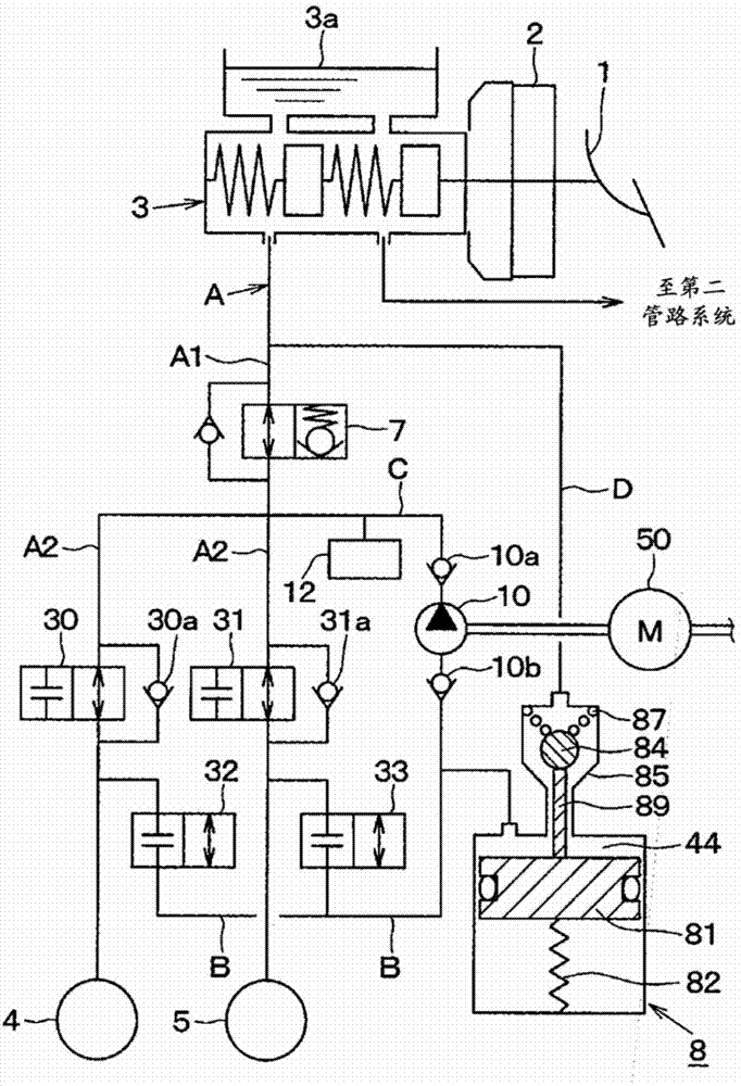
[0037] In addition, in a front-wheel drive four-wheel vehicle, this embodiment explains an example in which the pressure regulating accumulator of the present invention is applied to a front wheel drive four-wheel vehicle, wherein the pressure regulating accumulator constitutes an X-pipe configuration The hydraulic circuit of the X pipeline, the front right wheel-rear left wheel and the front left wheel-rear right wheel each have a pipeline system.

[0038] Such as figure 1 As shown in , the brake pedal 1 as a brake operation part is connected to the servo unit 2, and the driver depresses the brake pedal 1 when the braking force is applied to the vehicle, and the brake pedaling force is increased by the servo unit 2 .

[0039] The servo unit 2 has a push rod or the like that transmits increased brake pedaling force to the master cylinder 3 , and generates master cyli...


PUM


Abstract

A seal part that separates a first conduit line and a second conduit line is formed by contact between a peripheral surface of a pressure regulating valve and an inner wall surface of a housing. By forming a conduit line connected to a reservoir chamber among the second conduit line B is formed by the peripheral surface of the pressure regulating valve and the inner wall surface of the housing in a side of the reservoir chamber opposite to the seal part among the peripheral surface of the pressure regulating valve, the conduit line and the seal part do not overlap in a radial direction of the pressure regulating valve, thus the second conduit line can be disposed closer to the pressure regulating valve.

Description

technical field [0001] The present invention relates to a pressure regulating accumulator applied to brake fluid pressure control of vehicles such as ABS control and the like. Background technique [0002] Conventionally, there is a pressure regulating accumulator disclosed in, for example, Japanese Laid-Open Application Publication No. 2006-151362. [0003] refer to Figure 5 The pressure regulating accumulator disclosed in this gazette will be described. [0004] Such as Figure 5 As shown in , the pressure regulating accumulator has the following structure: the structure includes a valve J3, a valve seat J4, a filter member J5, a piston J6, Shaft J7, spring J8, stopper J9, etc. [0005] The valve J3, the valve seat J4, and the filter member J5 are assembled to constitute a pressure regulating valve, and the valve J3 is incorporated in the filter member J5 and the valve seat J4 when the filter member J5 and the valve seat J4 are fixed. [0006] Another spring J10 is pro...

Claims


Application Information

Patent Timeline
IPC IPC(8): B60T8/48
CPCB60T8/341B60T8/368B60T8/4872B60T13/146B60T13/662B60T13/686B60T15/36
Inventor 小山文利
Owner ADVICS CO LTD
Why Eureka
Try Eureka