
Electric control integrated motor

An integrated, electronically controlled technology, applied in electromechanical devices, electrical components, electrical components, etc., can solve the problems of large overall volume and poor integration, and achieve the effects of good integration, cost reduction, and good heat dissipation.

Pending Publication Date: 2021-02-26
浙江方远四福机电有限公司
View PDF0 Cites 0 Cited by
  • Summary
  • Abstract
  • Description
  • Claims
  • Application Information

AI Technical Summary

Problems solved by technology

[0003] In view of the above-mentioned related technologies, the inventor believes that in actual use, the controller is usually carried and fixed on the top of the motor, which makes the motor as a whole obviously have the controller protruding from the outside, poor integration and resulting in a larger overall volume

Method used


Image

  • Electric control integrated motor
  • Electric control integrated motor
  • Electric control integrated motor

Examples


Embodiment 1

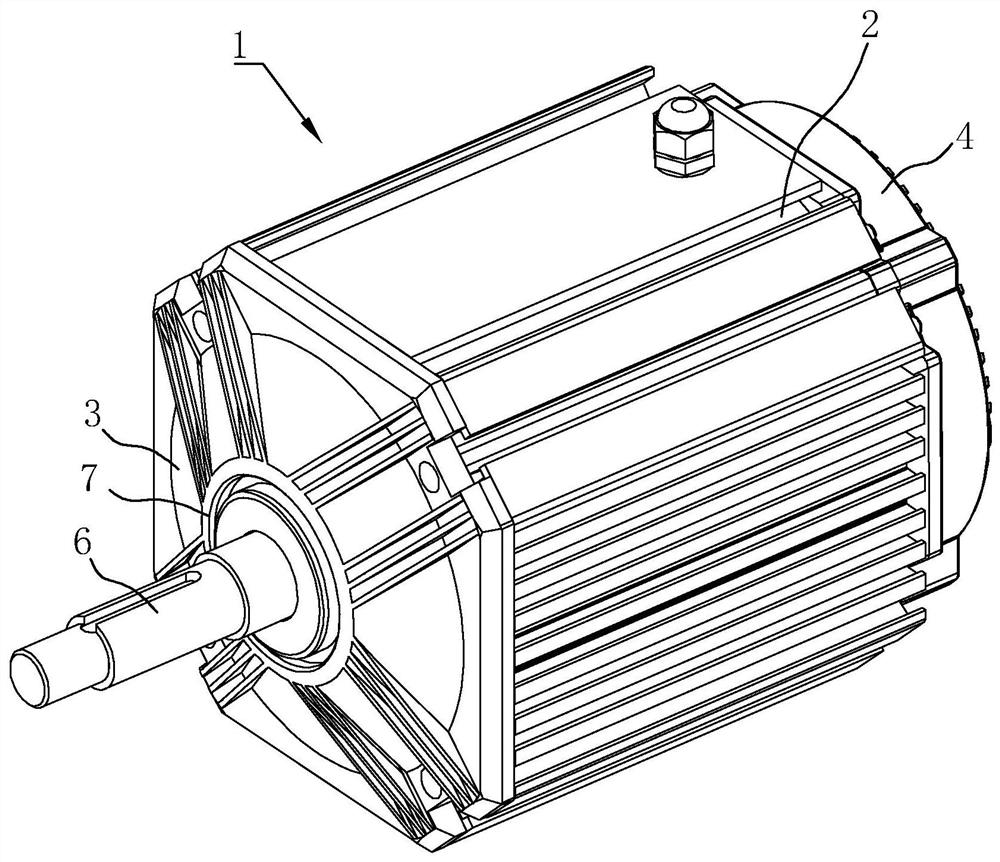
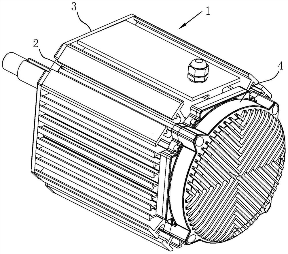
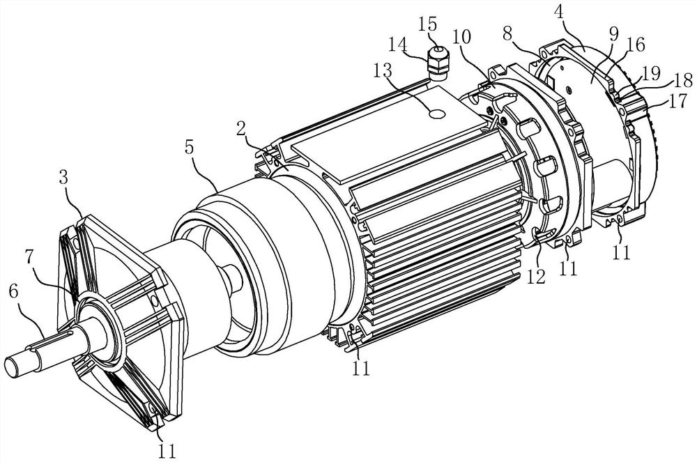
[0042] Electric control integrated motor, refer to figure 1 with figure 2 As shown, a body 1 is included, and the body 1 includes a casing 2, a front cover 3 and a rear cover 4. The surface of the cover 4 away from the front cover 3 is fixedly provided with cooling fins, and at the same time, the cooling performance of the motor as a whole is improved through the cooling of the cooling fins.

[0043] Such as figure 1 with image 3 As shown, a stator 5 and a rotor 6 are arranged inside the casing 2, and the center of the front cover 3 is provided with a perforation 7 for the rotor 6 to pass through, and one end of the rotor 6 passes through the perforation 7 to form the driving end of the motor; the rear cover 4 is formed with an installation cavity 8, the circuit board 9 of the controller is installed and fixed in the installation cavity 8, and the space inside the back cover 4 is rationally used to integrate the circuit board 9 of the controller into the whole motor, so t...

Embodiment 2

[0052] Electric control integrated motor, refer to Image 6 with Figure 7 The difference between this embodiment and Embodiment 1 is that the structure of the bearing mounting seat 10 is different. In this embodiment, the bearing mounting seat 10 is provided with a positioning hole 24 corresponding to the line head 14, and the positioning hole 24 runs through the bearing. The side wall of the mounting seat 10; the bottom end of the threading head 14 can be inserted into the positioning hole 24 in the process of rotating and tightening the threading head 14 to realize the positioning and locking of the bearing mounting seat 10. When the circuit board 9 is overhauled, after the nuts of the bolts in the mounting holes 11 are removed, the rear cover 4 can be moved away from the casing 2, during which the bearing mounting seat 10 will not be loosened from the casing 2, and the bearing The stability of the mounting seat 10 is convenient for the subsequent assembly of the back cove...


PUM


Abstract

The invention relates to an electric control integrated motor, which comprises a motor body, the motor body comprises a casing, a front cover and a rear cover, a mounting cavity is formed in the rearcover, and a circuit board of a controller is mounted in the mounting cavity. The circuit board of the controller is installed in the mounting cavity of the rear cover, the internal space of the rearcover is reasonably utilized, the controller is integrated in the whole motor, the controller does not need to be wholly carried on the top to occupy the space, the integration degree of the motor iseffectively improved, the overall size is effectively reduced, meanwhile, a shell of the controller can also be omitted, and the cost is effectively reduced.

Description

technical field [0001] The present application relates to the field of motors, in particular to an electronically controlled integrated motor. Background technique [0002] Motor, commonly known as motor, is an electromagnetic device that converts or transmits electric energy according to the law of electromagnetic induction. It is widely used in various occasions that require a rotating power source. It is usually used with a controller when it is used. The controller of the motor is An integrated circuit that controls the motor to work according to the set direction, speed, angle, and corresponding time through active work. [0003] Regarding the above-mentioned related technologies, the inventor believes that in actual use, the controller is usually carried and fixed on the top of the motor, which makes the motor as a whole obviously have the controller protruding from the outside, poor integration and resulting in a larger overall volume. Contents of the invention [...

Claims


Application Information

Patent Timeline
IPC IPC(8): H02K11/30H02K5/18H02K11/00H02K5/16H02K5/24H02K5/10C09D5/16C09D5/14C09D5/00B05D5/12B05D5/00
CPCB05D5/00B05D5/12C09D5/00C09D5/14C09D5/16H02K5/10H02K5/16H02K5/18H02K5/24H02K11/0094H02K11/30
Inventor 李增龄
Owner 浙江方远四福机电有限公司
Learn More