Multifunctional electric rail

A multi-functional, electric technology, applied in fences, lighting and heating equipment, buildings, etc., can solve the problems of single function, serious aging, complicated installation, etc., to achieve the effect of simple operation, reducing the degree of aging, and prolonging the service life

Inactive Publication Date: 2015-06-17
STATE GRID CORP OF CHINA +1
View PDF6 Cites 4 Cited by
  • Summary
  • Abstract
  • Description
  • Claims
  • Application Information

AI Technical Summary

Problems solved by technology

[0005] In order to solve the above technical problems, the present invention provides a multifunctional electric fence to solve the problems of single function, complicated installation, serious aging and low service life of the existing electric fence during use

Method used


Image

  • Multifunctional electric rail
  • Multifunctional electric rail
  • Multifunctional electric rail

Examples


Embodiment

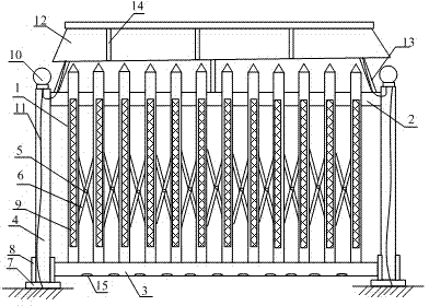
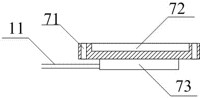
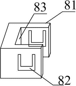
[0025] as attached figure 1 to attach image 3 shown

[0026] The present invention provides a multi-functional electric fence, which includes a vertical fence 1, a horizontal fence 2, a slide rail 3, a column 4, a rotating shaft 5, a diagonal stay rod 6, a base 7, a card frame 8, a reflective strip 9, a warning light 10, and a wire 11. Photovoltaic panels 12, poles 13, ventilation slots 14 and water leakage holes 15, the vertical column 1 is fixed between the columns 4 through the horizontal column 2 and the slideway column 3; the vertical column 1 is fixed by a rotating shaft 5 connected diagonal stay rod 6 is reinforced and fixed; the column 4 is installed in the base 7 on the upper part of the ground; the card frame 8 is fixedly connected with the slide column 3 and the column 4; the reflective strip 9 is attached to the vertical column 1; the warning light 10 is connected to the base 7 and the photovoltaic panel 12 through the wire 11; the photovoltaic panel 12 is inst...


PUM


Abstract

The invention provides a multifunctional electric rail. The multifunctional electric rail comprises vertical rails, a transverse rail, a slide way rail, stand columns, rotary shafts, diagonal draw bars, bases, clamping frames, light reflection strips, caution lamps, lead wires, photovoltaic plates, supporting rods, ventilation grooves and water leaking holes, wherein the vertical rails are fixed between the stand columns by the transverse rail and the slide way rails; the vertical rails are reinforced and fixed by the diagonal draw bars connected with the rotary shafts; the stand columns are mounted in the bases at the upper part of the ground; the clamping frames are used for fixedly connecting the slide way rail and the stand columns; the light reflection strips are adhered to the outer side surfaces of the vertical rails; and the caution lamps are connected with the bases and the photovoltaic plates by the lead wires. The bases, the clamping frames, the photovoltaic plates and the caution lamps are arranged so that the multifunctional property of the electric rail is easy to realize; and the multifunctional electric rail is simple and convenient to mount and convenient to adjust, has a strong caution effect and a long service life, and is convenient for market popularization and application.

Description

technical field [0001] The invention belongs to the field of isolation facilities, in particular to a multifunctional electric fence. Background technique [0002] Electric power facilities such as power supply and power distribution can often be seen on the side of the street, beside the house and along the highway. In order to prevent non-professionals from accidentally touching the power facilities and avoid electric shock accidents, the power supply department generally arranges power fences around the power facilities. There are many types of electric fences with different purposes, but their structures are basically the same. [0003] The Chinese patent publication number is CN 204081644 U, and the name of the invention is a new type of maintenance-free environmental protection electric fence. Each vertical column is composed of PVC pipe A and steel square pipe A embedded in pipe A, and each horizontal column is composed of PVC pipe B and steel square pipe B embedded...

Claims


Application Information

Patent Timeline
Patent Type & Authority Applications(China)
IPC IPC(8): E04H17/14E01F9/015E01F9/016E01F9/03E01F9/615E01F9/619E01F9/669
CPCE04H17/14E04H17/1447F21V33/00
Inventor 李春明许强赵风西成方刚崔健王涛张营
Owner STATE GRID CORP OF CHINA
Why Eureka
Try Eureka