Solid-propellant rocket engine capable of being ignited at tail

A rocket motor, solid fuel technology, applied in rocket motor devices, machines/engines, mechanical equipment, etc., can solve the problems of difficult to achieve ignition and combustion, unstable working performance of rocket motors, difficult to ignite, etc., to achieve convenient implementation, structure Simple, stable performance

Active Publication Date: 2015-06-17
AEROSPACE LIFE SUPPORT IND LTD
View PDF5 Cites 7 Cited by
  • Summary
  • Abstract
  • Description
  • Claims
  • Application Information

AI Technical Summary

Problems solved by technology

The tail ignition can only ignite the solid fuel at the tail of the rocket first, and it is difficult to achieve ignition and combustion, resulting in uns

Method used


Image

  • Solid-propellant rocket engine capable of being ignited at tail
  • Solid-propellant rocket engine capable of being ignited at tail
  • Solid-propellant rocket engine capable of being ignited at tail

Examples


Embodiment Construction

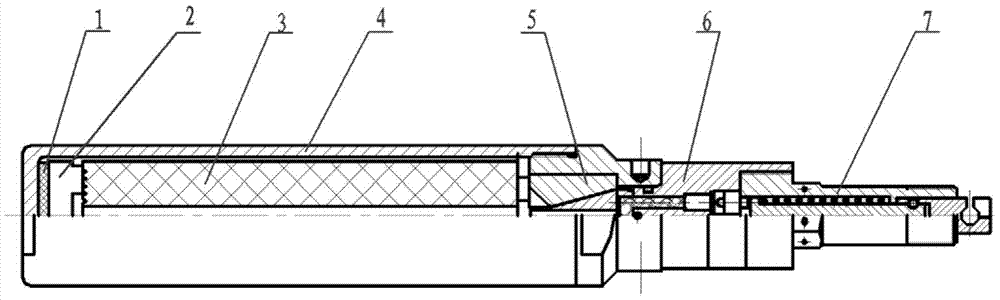
[0019] Such as figure 1 The shown embodiment of the solid fuel rocket motor capable of tail ignition of the present invention includes a combustion chamber 4, a nozzle assembly 5 and a solid fuel 3, the nozzle assembly 5 is arranged at the tail end of the combustion chamber 4, and the solid fuel 3 is arranged on the combustion chamber. In the chamber 4; it is characterized in that: the solid fuel rocket engine also includes an ignition box 2, an ignition tool 6 and its firing mechanism 7, the ignition box 2 is arranged at the front end of the solid fuel in the combustion chamber, and the ignition tool 6 is arranged at the nozzle assembly 5 end of . A buffer pad 1 is provided between the front end of the combustion chamber and the ignition box to compensate for changes in the length of the solid fuel 3 due to temperature.

[0020] The present invention is a two-stage ignition mode composed of an igniter 6 installed at the tail of the rocket and an ignition box installed at the...


PUM


Abstract

The invention relates to a solid-propellant rocket engine capable of being ignited at a tail. The solid-propellant rocket engine comprises a combustion chamber, a spraying pipe component and a solid fuel, wherein the spraying pipe component is arranged at the tail end of the combustion chamber; and the solid fuel is arranged in the combustion chamber. The solid-propellant rocket engine further comprises an ignition box, an ignition tool and a firing mechanism thereof; the ignition box is arranged at the front end of the solid fuel in the combustion chamber; the ignition tool is arranged at the tail end of the spraying pipe component; the solid fuel is a cylinder; a gap is left between the outer side wall of the solid fuel and the inner side wall of the combustion chamber; and the spraying pipe combustion chamber end of the spraying pipe component is aligned to a center pipe of the solid fuel cylinder. The solid-propellant rocket engine can realize the mechanical firing and the tail ignition, can firstly ignite the solid fuel at the head of a rocket, and is stable in working performance.

Description

technical field [0001] This invention relates to solid fuel rocket motors. Background technique [0002] Existing solid fuel rocket motors all adopt the head ignition method. This ignition method can first ignite the solid fuel in the rocket head, which is easier to ignite and burn, and the rocket engine has stable working performance. At present, the head ignition method usually uses electric shock. In some cases, the structural characteristics of the product require the use of a mechanical method to fire the rocket, and the direction of the rocket's movement is opposite to the direction of the mechanical force for starting. For this reason, only the tail ignition method is adopted. The tail ignition can only ignite the solid fuel at the tail of the rocket first, and it is difficult to achieve ignition and combustion, resulting in unstable rocket engine performance, especially for solid rocket engines with low burning rate propellants and high packing density. It is more d...

Claims


Application Information

Patent Timeline
IPC IPC(8): F02K9/08F02K9/95
Inventor 马金贵赵迎春
Owner AEROSPACE LIFE SUPPORT IND LTD
Why Eureka
Try Eureka