Heavy double-column vertical lathe cross beam gravity deformation prediction method based on finite difference method

A technology of finite difference method and gravity deformation, applied in the direction of large fixed members, program control, instruments, etc., can solve the problems of large difference in actual deformation value, accurate calculation of beam gravity deformation curve, etc., to reduce the number of repairs, reduce installation costs and The effect of installation man-hours

Active Publication Date: 2015-06-17
HARBIN INST OF TECH
View PDF2 Cites 9 Cited by
  • Summary
  • Abstract
  • Description
  • Claims
  • Application Information

AI Technical Summary

Problems solved by technology

[0006] The purpose of the present invention is to solve the problem that the existing finite element analysis calculation method cannot accurately calculate the gravity deformation curve of the beam under the condition that the actual material properties are not uniform, resulting in a large difference between the calculation result and the actual deformation value. Prediction method of gravity deformation of heavy-duty double-column vertical car beam based on difference method

Method used


Image

  • Heavy double-column vertical lathe cross beam gravity deformation prediction method based on finite difference method
  • Heavy double-column vertical lathe cross beam gravity deformation prediction method based on finite difference method
  • Heavy double-column vertical lathe cross beam gravity deformation prediction method based on finite difference method

Examples


specific Embodiment approach 1

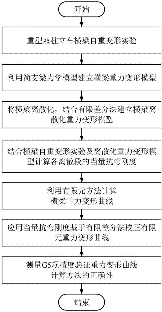
[0027] In the method for predicting the gravity deformation of the beam of a heavy-duty double-column vertical car based on the finite difference method in this embodiment, the calculation method for the gravity deformation curve of the beam is realized through the following steps:

[0028] Step 1: Simulate the actual assembly conditions to design the self-weight deformation experiment of the heavy-duty machine tool beam, and obtain the self-weight deformation curve of the beam under the condition of uneven material;

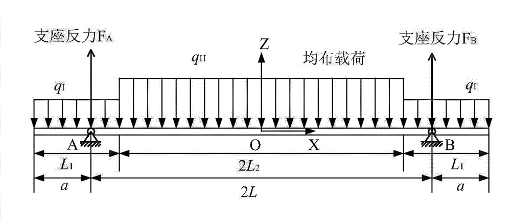
[0029] Step 2: Using the theory of material mechanics, simplify the beam into a simply supported beam mechanical model according to the force of the beam under its own weight;

[0030] Step 3: discretize the beam into a group of discrete micro-segments, discretize the mechanical model of the simply supported beam obtained in step 2, and then combine the finite difference method to establish a discretization model of the gravity deformation of the beam;

[0031] ...

specific Embodiment approach 2

[0034] The difference from the specific embodiment 1 is that in the method for predicting the gravity deformation of the beam of the heavy-duty double-column vertical car based on the finite difference method in this embodiment, the self-weight deformation experiment of the beam of the heavy-duty machine tool described in step 1 is specifically as follows:

[0035] Step 11. According to the shape of the beam, take the midpoint of the beam in the horizontal plane where the beam is located as the origin O of the coordinate system, and establish a Cartesian coordinate system. The direction of the X-axis is along the direction of the guide rail of the beam, and positive to the right, and the Y-axis is perpendicular to the X-axis. And upward is positive, and the positive direction of the Z axis conforms to the right-hand rule; figure 2 shown;

[0036] Step 12: Lay the beam horizontally, and use an autocollimator to measure the Z-direction straightness data on the surface of the gu...

specific Embodiment approach 3

[0038] The difference from the specific embodiment 1 or 2 is that the method for predicting the gravitational deformation of the beam of the heavy-duty double-column vertical car based on the finite difference method in this embodiment, the method for obtaining the self-weight deformation curve of the beam described in step 1 is specifically:

[0039] The difference between the Z-direction straightness measured after placing the beam on the side described in step 13 until the deformation is stable and the Z-direction straightness data measured after placing the beam horizontally as described in step 12, and using the difference to draw the The self-weight deformation curve of the beam described above.


PUM


Abstract

The invention relates to a heavy double-column vertical lathe cross beam gravity deformation prediction method based on a finite difference method. Due to the fact that an existing finite element analysis computing method cannot accurately calculate a cross beam gravity deformation curve on the condition that actual materials have not uniform attributes, the calculation result much differs from an actual deformation value. The heavy double-column vertical lathe cross beam gravity deformation prediction method based on the finite difference method comprises the steps that actual assembling conditions are simulated to design a heavy machine tool cross beam self-weight deformation experiment to obtain a self-weight deformation curve. By means of the material mechanical theory, a cross beam is simplified into a simply supported beam mechanical model and then made into micro segments through discretization, and a cross beam gravity deformation discretization model is built on the basis of the finite difference method; the equivalent weight bending rigidity of each discrete micro segment is calculated; the cross beam finite element gravity deformation curve is calculated; the equivalent weight bending rigidity is utilized for correcting the cross beam finite element gravity deformation curve on the basis of the finite difference method to obtain a final cross beam gravity deformation curve. The heavy double-column vertical lathe cross beam gravity deformation prediction method is applied to heavy double-column vertical lath cross beam gravity deformation curve calculation.

Description

technical field [0001] The invention relates to a method for predicting the gravitational deformation of a beam of a heavy-duty double-column vertical vehicle based on a finite difference method. Background technique [0002] Heavy-duty CNC machine tools are widely used in key fields such as national defense, aerospace, energy, ships, and metallurgy as processing machines. The quality of their precision directly reflects the level of a country's manufacturing industry. Due to the structural factors such as large size and large span of the heavy-duty double-column vertical lathe itself, it will cause a certain degree of deformation under its own gravity, and the deformation error caused by the gravity cannot be ignored. [0003] The beam is the core component of the heavy-duty double-column vertical lathe, and the parallelism of the vertical tool holder movement to the worktable (G5 item accuracy) is its most important accuracy index. By compensating the anti-deformation cur...

Claims


Application Information

Patent Timeline
Patent Type & Authority Applications(China)
IPC IPC(8): G05B19/401B23Q1/01
CPCB23Q1/015G05B19/401
Inventor 韩振宇邵忠喜王瀚富宏亚
Owner HARBIN INST OF TECH
Why Eureka
Try Eureka