Heavy planomiller beam gravity deformation predicting method based on finite difference method

A finite difference method and gravity deformation technology, which is applied in special data processing applications, instruments, electrical digital data processing, etc., can solve the problems of large difference in actual deformation values, accurate calculation of beam gravity deformation curve, etc.

Active Publication Date: 2015-05-20
HARBIN INST OF TECH
View PDF2 Cites 4 Cited by
  • Summary
  • Abstract
  • Description
  • Claims
  • Application Information

AI Technical Summary

Problems solved by technology

[0006] The purpose of the present invention is to solve the problem that the existing finite element analysis calculation method cannot accurately calculate the gravity deformation curve of the beam under the condition that the actual materi

Method used


Image

  • Heavy planomiller beam gravity deformation predicting method based on finite difference method
  • Heavy planomiller beam gravity deformation predicting method based on finite difference method
  • Heavy planomiller beam gravity deformation predicting method based on finite difference method

Examples


specific Embodiment approach 1

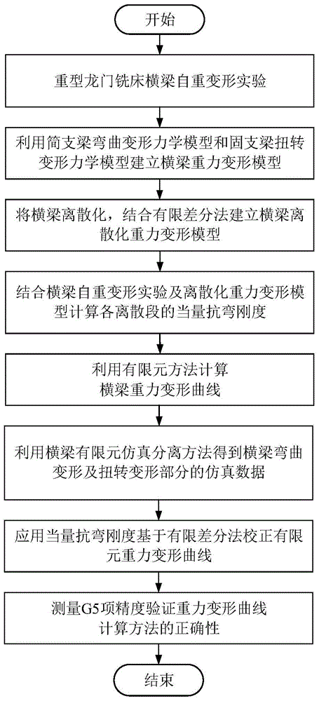
[0035] Specific Embodiment 1: A method for predicting the gravitational deformation of a beam of a heavy-duty gantry milling machine based on the finite difference method in this embodiment is specifically prepared according to the following steps:

[0036] Step 1. By placing shim iron at the assembly place of the beam and the column, simulating the actual assembly conditions to design the self-weight deformation experiment of the heavy-duty machine tool beam, and obtain the self-weight deformation curve of the beam considering the material inhomogeneity;

[0037] Step 2. Using the theory of material mechanics, the beam is simplified into a beam self-weight deformation model and a beam torsional deformation model according to the stress of the beam under its own weight;

[0038]Step 3. Discretize the beam into a group of discrete micro-segments. After discretizing the self-weight deformation model of the beam obtained in Step 2, combine the finite difference method to establish...

specific Embodiment approach 2

[0047] Specific embodiment 2: The difference between this embodiment and specific embodiment 1 is that in step 1, by placing pad iron at the assembly place of the beam and the column, simulating the actual assembly conditions to design the self-weight deformation experiment of the beam of the heavy-duty machine tool, and obtaining the material inhomogeneity The specific process of the self-weight deformation curve of the beam is as follows:

[0048] (1) According to the top view of the beam of the heavy-duty gantry milling machine, the midpoint of the beam in the horizontal plane where the lower guide rail of the beam is located is taken as the origin O of the coordinate system, and the Cartesian coordinate system is established. The X-axis direction is along the direction of the beam guide rail, and the positive and Y axes are to the right Perpendicular to the X-axis, and upward is positive and the positive direction of the Z-axis conforms to the right-hand rule as image 3 s...

specific Embodiment approach 3

[0053] Embodiment 3: The difference between this embodiment and Embodiment 1 or 2 is that in step 2, the theory of material mechanics is used to simplify the beam into a deformation model of the weight of the beam and a torsional deformation model of the beam according to the force of the beam under its own weight. The process is:

[0054] (1) According to figure 2 The shape of the beam is simplified by using the calculation method of material mechanics to simplify the calculation model, and according to the working environment and assembly constraints of the machine tool beam, the bending deformation part of the beam is simplified as a simply supported beam;

[0055] (2) Gravity is applied to the simply supported beam as a uniformly distributed load, and the uniformly distributed load is expressed by the gravity on the unit length of the beam, that is, the concentration of gravity load; Figure 6 The mechanical model of simply supported beam;

[0056] (3) According to the s...


PUM


Abstract

The invention provides and relates to a heavy planomiller beam gravity deformation predicting method based on the finite difference method. The heavy planomiller beam gravity deformation predicting method aims at solving the problems that by means of an existing finite element analyzing and calculating method, the beam gravity deformation curve can not be accurately calculated under the condition that actual material properties are not uniform and then the difference between the calculation result and the actual deformation value is large. The method includes the steps of firstly, obtaining the beam gravity deformation curve; secondly, simplifying the beam gravity deformation curve into a beam gravity deformation model and a beam torsional deformation model; thirdly, establishing a beam gravity deformation discrete model; fourthly, calculating the equivalent flexural rigidity; fifthly, obtaining a beam finite element gravity deformation curve; sixthly, separating the finite element gravity deformation curve; seventhly, obtaining the final beam gravity deformation curve. The method is applied to the prediction of the heavy planomiller beam gravity deformation.

Description

technical field [0001] The invention relates to a method for predicting gravity deformation of a beam of a heavy-duty gantry milling machine, in particular to a method for predicting the gravity deformation of a beam of a heavy-duty gantry milling machine based on a finite difference method. Background technique [0002] Heavy-duty CNC machine tools are widely used in key fields such as national defense, aerospace, energy, ships, and metallurgy as processing machines [1]. level of manufacturing. Due to structural factors such as the large size and large span of the beam of the heavy-duty gantry milling machine, it will cause a certain degree of deformation under its own gravity, and the deformation error caused by the gravity cannot be ignored. [0003] The beam is the core component of the heavy-duty gantry milling machine, and the parallelism of the vertical tool holder movement to the worktable (G5 accuracy) is its most important accuracy index. By compensating the anti...

Claims


Application Information

Patent Timeline
IPC IPC(8): G06F17/50
Inventor 韩振宇邵忠喜王瀚富宏亚
Owner HARBIN INST OF TECH
Why Eureka
Try Eureka