A time-to-digital converter in a phase-locked loop

A technology of time-to-digital converters, applied in the field of phase-locked loops, can solve the problems of low phase-locking precision of phase-locked loops, and achieve the effects of easy implementation, improved phase-locked accuracy, and improved detection accuracy

Active Publication Date: 2018-10-02
HUAWEI TECH CO LTD
View PDF5 Cites 0 Cited by
  • Summary
  • Abstract
  • Description
  • Claims
  • Application Information

AI Technical Summary

Problems solved by technology

[0008] An embodiment of the present invention provides a time-to-digital converter in a phase-locked loop to solve the problem of low phase-locking precision of the phase-locked loop

Method used


Image

  • A time-to-digital converter in a phase-locked loop
  • A time-to-digital converter in a phase-locked loop
  • A time-to-digital converter in a phase-locked loop

Examples


Embodiment 1

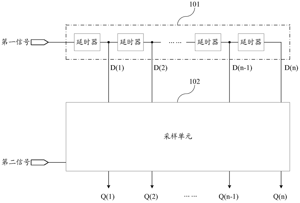
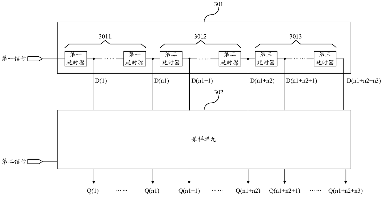
[0045] Embodiment 1 of the present invention provides a time-to-digital converter in a phase-locked loop, such as image 3 As shown, it includes a delay unit 301 that inputs the first signal and a sampling unit 302 that inputs the second signal, wherein:

[0046] The delay unit 301 includes a first delay chain 3011, a second delay chain 3012 and a third delay chain 3013 connected in series, for delaying the first signal; the first delay chain 3011 includes at least one The first delayer, the second delay chain 3012 includes at least three second delayers, the third delay chain 3013 includes at least one third delayer, the delay length of the first delayer and the third delayer The delay length of the timer is greater than the delay length of the second delayer;

[0047] The sampling unit 302 is used to delay each of the first delayers in the first delay chain 3011 in the delay unit 301 and each second delay in the second delay chain 3012 at the preset moment of the second sig...

Embodiment 2

[0066] Based on the same inventive concept, the structure of the time-to-digital converter in the phase-locked loop provided by Embodiment 1 of the present invention is simplified, and Embodiment 2 of the present invention also provides a time-to-digital converter in the phase-locked loop, such as Figure 6 As shown, it includes a delay unit 601 that inputs the first signal and a sampling unit 602 that inputs the second signal, wherein:

[0067] The delay unit 601 includes a first delay chain 6011 and a second delay chain 6012 connected in series, for delaying the first signal; the first delay chain 6011 includes at least one first delayer, and the second delay The time chain 6012 includes at least three second delayers, the delay length of the first delayer is greater than the delay length of the second delayer;

[0068] The sampling unit 602 is used to delay each first delayer in the first delay chain 6011 in the delay unit 601 and each second delay in the second delay chain...


PUM


Abstract

The invention discloses a time-to-digital converter in a phase-locked loop, which can improve phase-locking precision. The time-to-digital converter includes a delay unit for inputting a first signal and a sampling unit for inputting a second signal, wherein: the delay unit includes a first delay chain, a second delay chain and a third delay chain in series The chain is used to delay the first signal; the first delay chain includes at least one first delayer, the second delay chain includes at least three second delayers, and the third delay chain includes at least one first delayer Three delayers, the delay length of the first delayer and the delay length of the third delayer are greater than the delay length of the second delayer; the sampling unit is used for the preset moment of the second signal, for The output signals of each first delayer in the first delay chain in the delay unit, each second delayer in the second delay chain and each third delayer in the third delay chain are carried out Sample, output the sampled signal.

Description

technical field [0001] The invention relates to the technical field of phase-locked loops, in particular to a time-to-digital converter in the phase-locked loop. Background technique [0002] Phase-locked loops (PLL, Phase-locked loops) is a technology that utilizes a feedback control principle to realize a constant phase difference between two signals. For example, for two signals, the first signal and the second signal, the target phase difference of the two signals can be given arbitrarily, that is, given the target time interval between the specified moment of the first signal and the preset moment of the second signal, two signals can be detected. The current phase difference of the signal, that is, the current time interval between the specified moment of detecting the first signal and the preset moment of the second signal, when the second signal is used as a reference signal, the first The phase of the signal is controlled to lock the time interval between the desig...

Claims


Application Information

Patent Timeline
Patent Type & Authority Patents(China)
IPC IPC(8): H03L7/081H03L7/091
CPCG04F10/005H03L7/085H03L7/0818H03L7/095H03L7/197
Inventor 周盛华宋冉
Owner HUAWEI TECH CO LTD
Why Eureka
Try Eureka