Phase-locked loop based on equivalent phase demodulation frequency

A phase detection frequency and phase-locked loop technology, applied in the field of phase-locked loops, can solve the problems of low reliability, high cost, complex phase-locking equipment, etc., and achieve the effects of low cost, simplified circuits, and reduced phase noise.

Inactive Publication Date: 2013-01-23
XIDIAN UNIV
View PDF0 Cites 0 Cited by
  • Summary
  • Abstract
  • Description
  • Claims
  • Application Information

AI Technical Summary

Problems solved by technology

The traditional method uses a lot of frequency multipliers and mixers to expand the locked frequency range, which makes the phase-locked equipment complicated, expensive, and unreliable

Method used


Image

  • Phase-locked loop based on equivalent phase demodulation frequency
  • Phase-locked loop based on equivalent phase demodulation frequency
  • Phase-locked loop based on equivalent phase demodulation frequency

Examples


Embodiment Construction

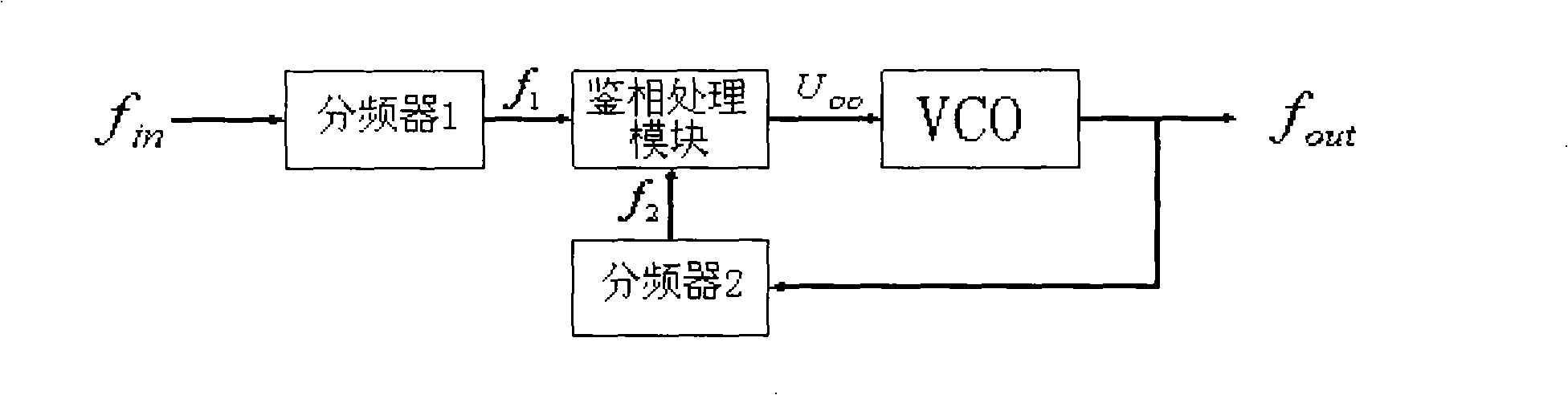
[0025] like figure 1 As shown, it is the functional block diagram of the phase-locked loop based on the equivalent phase detection frequency. The specific design of the phase-locked loop based on the equivalent phase detection frequency is divided into the following modules:

[0026] 1) Tested signal frequency divider and reference signal frequency divider

[0027] The input signal enters the stagger phase detector after passing through the measured signal frequency divider and the reference signal frequency divider. The frequency division value of the measured signal frequency divider and the reference signal frequency divider is controlled by an external single-chip microcomputer. The frequency division value is input into the frequency divider in the form of 8-bit data. The design of the frequency divider is done in CPLD (Complex Programmable Logic Device). Here we need to consider how to use f in and f out The frequency values ​​of frequency divider 1 and frequency div...


PUM


Abstract

The invention relates to a phase-locked loop, in particular to a phase-locked loop based on equivalent phase demodulation frequency. The phase-locked loop is characterized by at least comprising a detected signal frequency divider, a reference signal frequency divider, a phase demodulation processing module and a voltage controlled oscillator, wherein the detected signal frequency divider and thereference signal frequency divider are used for frequency division for a detected signal and a reference signal to make the equivalent phase demodulation frequency of the detected signal and the reference signal which are acquired by the frequency division be 5 MHz; the phase demodulation processing module finishes the phase demodulation of a signal of the detected signal passing through the frequency divider and a signal of the reference signal passing through the frequency divider, and outputs a control voltage for controlling the voltage controlled oscillator; and the voltage controlled oscillator is used for controlling oscillation signals output by the voltage. The frequency division values of the detected signal frequency divider and the reference signal frequency divider are controlled by an external singlechip, and the singlechip inputs the needed frequency division values into the frequency dividers in form of 8bit data. The voltage controlled oscillator is a voltage controlled crystal oscillator of 5MHz, an input end of the oscillator is electrically connected with an output end of an amplifying and shaping module, and an output end of the oscillator is electrically connected with an input end of the detected signal frequency divider.

Description

technical field [0001] The invention relates to a phase-locked loop, in particular to a phase-locked loop based on an equivalent phase-discrimination frequency. Background technique [0002] At present, the phase-locked loop technology used at home and abroad has such characteristics: use the reference signal to control the frequency and phase of the loop oscillating signal, so that the oscillating signal can track the frequency and phase of the reference signal. When the frequencies of the two are completely equal, the considered locked. This phase-locked loop circuit can be divided into three types, namely, analog phase-locked loop (APLL), digital phase-locked loop (DPLL) and software phase-locked loop with memory capability (microcomputer control). A phase-locked loop usually consists of three parts: a phase detector (PD), a loop filter (LF) and a voltage-controlled oscillator (VCO). The traditional analog phase-locked loop (APLL) has a short locking time to ensure the ...

Claims


Application Information

Patent Timeline
Patent Type & Authority Patents(China)
IPC IPC(8): H03L7/085H03L7/089
Inventor 周渭王海高建宁陈发喜孙江涛于光运
Owner XIDIAN UNIV
Why Eureka
Try Eureka