Pull-out guide

A technology for pulling out guides and components, applied to furniture parts, household heating, bearings, etc., can solve problems such as cancellation, large tolerance, fuzzy determination of clamping force, etc.

Inactive Publication Date: 2015-06-17
PAUL HETTICH
View PDF8 Cites 8 Cited by
  • Summary
  • Abstract
  • Description
  • Claims
  • Application Information

AI Technical Summary

Problems solved by technology

With this arrangement the slide rails can be locked in one or more positions, however, the snap-in force can only be determined vaguely, because especially in the case of a full extension with at least three rails, two snap-in members, one of the two snap-in members must be disengaged to move the slide rail
Which snap-in member acts with which snap-in force is not defined, so that there are large tolerances in the force for moving out of the snap-in position
In addition, there is the problem that during retraction or extension of the slide, the lock must be canceled in the middle position, which is considered annoying during continuous movement

Method used


Image

  • Pull-out guide
  • Pull-out guide
  • Pull-out guide

Examples


Embodiment Construction

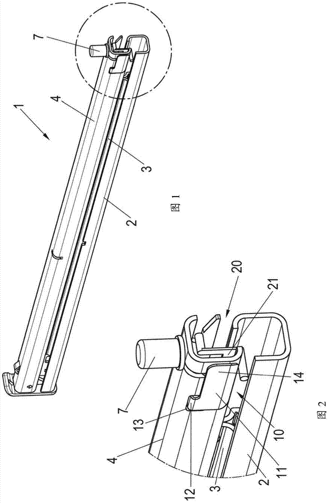
[0027] The pull-out guide 1 comprises a rail 2 which can be fastened to the main body of a piece of furniture or a household appliance and is usually arranged in a fixed manner, a rail 3 embodied as an intermediate rail, and a rail 4 (also called a sliding rail), on which Pushing elements (such as drawers, cooking material holders or other components) are mounted on them to make them movable.

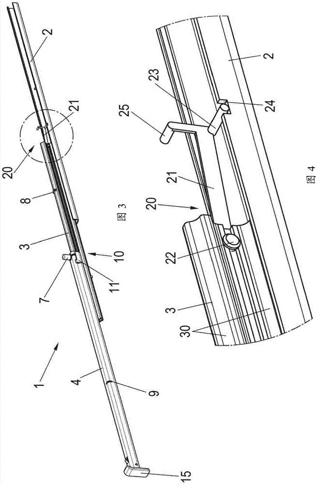
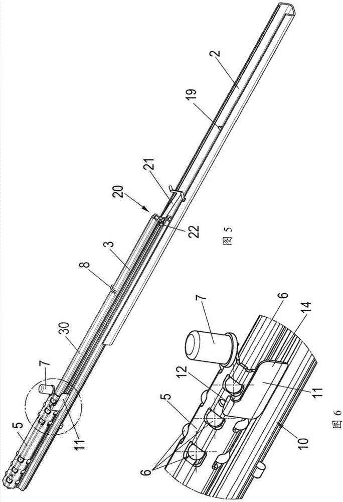
[0028] Such as figure 2 As shown in , the snap-in mechanism 10 is located on the first track 4 , the snap-in mechanism 10 has a bendable elastic element 11 , and the elastic element 11 engages with the protrusion 12 through the opening 13 in the first track 4 . Furthermore, a locking mechanism 20 is provided which acts between the second rail 3 and the third rail 2 . Of course, it is also possible to arrange the engaging mechanism 10 on the second rail 3 or the third rail 2 and arrange the locking mechanism on the first rail 4 . Only the exemplary embodiments shown are explained belo...


PUM


Abstract

A pull-out guide (1, 1', 1", 1"'), in particular for domestic appliances or furniture, comprises at least three rails (2, 3, 4) that are mounted so as to be movable relative to each other, one rail (2) being securable to a body and another rail (4) being connectible to a pull-out element, and a detent mechanism (10) for locking a first rail (4) in a predetermined position relative to a second rail (3), a locking mechanism (20, 40, 50, 70, 70') being provided for locking the second rail (3) relative to a third rail (2) in the predetermined position against movement. The pull-out guide according to the invention can thus be moved according to a defined sequence control and with exact detent forces.

Description

technical field [0001] The invention relates to a pull-out guide, in particular for household appliances or furniture, comprising at least three rails mounted movable relative to each other, one of which can be fixed to the body, one The track may be connected to the push member, the pullout guide including a snap mechanism to lock the first track in a predetermined position relative to the second track. Background technique [0002] WO 2010 / 060724 discloses a pull-out guide in which snap-in means are provided between the individual rails, which snap-in means enable the movable slide rail to be locked in the pull-out position. In this case, the snap-in member comprises an elastic element which can be fixed on a corresponding snap-in groove or protrusion. With this arrangement the slide rails can be locked in one or more positions, however, the snap-in force can only be determined vaguely, because especially in the case of a full extension with at least three rails, two Cat...

Claims


Application Information

Patent Timeline
Patent Type & Authority Applications(China)
IPC IPC(8): A47B88/10F24C15/16A47B88/493
CPCA47B2210/0072A47B2210/17F24C15/168A47B88/493F16C29/046F16C29/048F16C29/10
Inventor 尤尔根·巴霍尔P·耶尔林格丹尼尔·雷哈格丹尼尔·里德S·巴斯科夫斯基埃德加·弗罗比埃特尔马蒂亚斯·库恩施克里斯蒂安·科尔德威
Owner PAUL HETTICH
Why Eureka
Try Eureka