Modified bus-bar joint device of subway tunnel

A joint device and bus bar technology, which is applied in the field of subway tunnels, can solve the problems that the anti-flooding door cannot break the wire rope, the movable joint cannot move, and the wire rope is easy to get stuck, so as to achieve good use effect, save time and improve safety. Effect

Inactive Publication Date: 2015-06-24
ZHEJIANG OCEAN UNIV
View PDF6 Cites 1 Cited by
  • Summary
  • Abstract
  • Description
  • Claims
  • Application Information

AI Technical Summary

Problems solved by technology

[0006] However, in actual use, the closing force of the anti-flooding door may not be able to break the wire rope. At the same time, due to the installation of too many pulleys, the wire rope is easy to get stuck, resulting in the inability of the moving joint to move, which leads to the failure of the connecting section to fall smoothly.

Method used


Image

  • Modified bus-bar joint device of subway tunnel
  • Modified bus-bar joint device of subway tunnel
  • Modified bus-bar joint device of subway tunnel

Examples


Embodiment 1

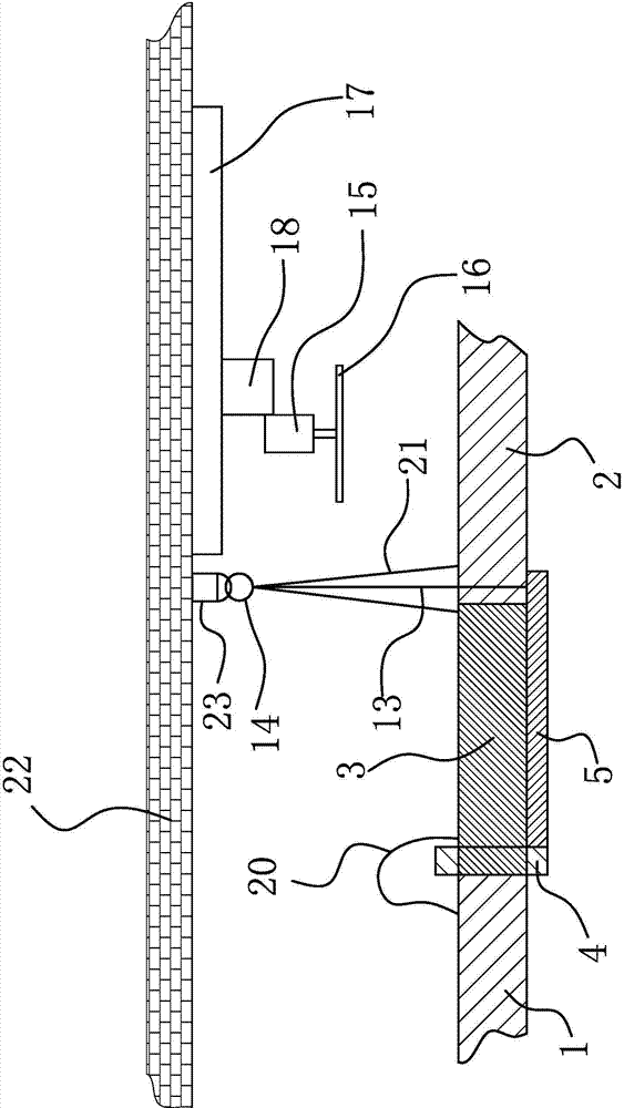
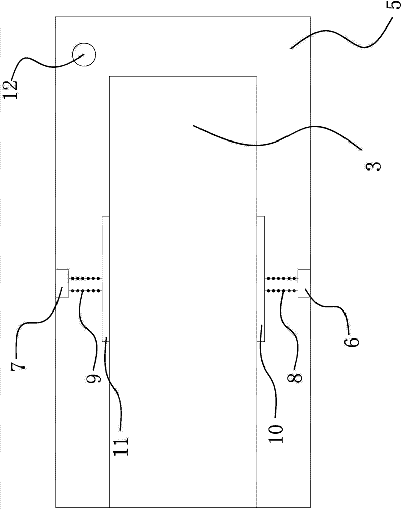
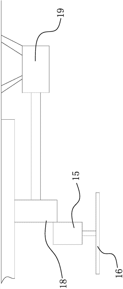
[0028] Such as figure 1 , figure 2 and image 3 As shown, the subway tunnel includes a tunnel body, and the tunnel body is provided with an anti-flooding door capable of closing the tunnel body; the bus bar joint device includes a bus bar left section 1, a bus bar right section 2 and a In connection with the connecting section 3, the floodproof door is hinged on the inner wall of the tunnel body, the connecting section 3 is located at the closing track of the floodproof door, and the left section 1 of the busbar is fixed with a positioning plate 4, The positioning plate 4 is provided with a piercing hole, the lower part of the positioning plate 4 is hinged with a support plate 5, and the other end of the support plate 5 is provided with a support plate that can make this end of the support plate 5 lean against the right side of the bus bar. The positioning structure at the lower part of section 2, the connecting section 3 is arranged on the support plate 5, one end of the c...

Embodiment 2

[0035] The content in the second embodiment is roughly the same as that in the first embodiment, the difference is that the lower part of the positioning plate 4 in the first embodiment is vertically fixed with a mounting block 1 and a mounting block 2, and the mounting block 1 and the mounting block 2 Mounting hole 1 and mounting hole 2 are respectively opened on the mounting block 2. One end of the support plate 5 is fixed with a hinged shaft, and the mounting hole 1 and mounting hole 2 are respectively fixed with a positioning bearing 1 and a positioning bearing 2. The hinged shaft described above is arranged between the mounting block 1 and the mounting block 2, and the two ends of the hinged shaft are respectively fixed on the inner ring of the positioning bearing 1 and the inner ring of the positioning bearing 2; and in the second embodiment, The lower part of the positioning plate 4 is vertically fixed with a mounting block 1 and a mounting block 2, and the mounting bloc...


PUM


Abstract

The invention provides a modified bus-bar joint device of a subway tunnel. The modified bus-bar joint device of the subway tunnel solves the technical problem that the connection section of a bus-bar joint device in an existing subway tunnel can not drop smoothly. The modified bus-bar joint device of the subway tunnel comprises a bus-bar left section, a bus-bar right section and a connection section located between the bus-bar left section and the bus-bar right section and used for connection, wherein the connection section is detachably arranged between the bus-bar left section and the bus-bar right section; a flood gate is hinged to the inner wall of a tunnel body; the connection section is located at the gate closing track of the flood gate. The modified bus-bar joint device of the subway tunnel has the advantages of saving time, being higher in efficiency, good in stability and safe in use, and the like.

Description

technical field [0001] The invention relates to a subway tunnel, in particular to an improved bus bar joint device of the subway tunnel. Background technique [0002] With the rapid development of my country's urban rail transit construction, the form of rigid suspension catenary is widely used. Rigid suspension catenary is a system composed of catenary wires embedded in head-to-tail busbars. It is an important equipment for power supply of electrified railway locomotives and rail transit vehicles. Its quality directly affects the operation of locomotives. [0003] Anti-flood doors are designed in the construction of urban subway tunnels. In the event of war and serious water leakage, it is necessary to quickly close the anti-flood doors and anti-flood doors of the tunnel to ensure the safety of the tunnel and personnel. However, under the blockage of the busbar, the anti-flood door cannot be completely closed, and special personnel need to be sent into the tunnel to remove...

Claims


Application Information

Patent Timeline
IPC IPC(8): B60M1/12B60M1/24
Inventor 高华喜
Owner ZHEJIANG OCEAN UNIV
Why Eureka
Try Eureka