Push organization

A push mechanism and linkage mechanism technology, applied in the field of packaging, can solve problems such as low efficiency and slow speed

Inactive Publication Date: 2016-10-05
长沙金属狂潮农用机械科技有限公司 +1
View PDF7 Cites 0 Cited by
  • Summary
  • Abstract
  • Description
  • Claims
  • Application Information

AI Technical Summary

Problems solved by technology

[0004] The purpose of the present invention is to provide a pushing mechanism to solve the problems of slow speed and low efficiency caused by manually pushing raw materials into the packing machine introduced in the background technology

Method used


Image

  • Push organization
  • Push organization
  • Push organization

Examples


Embodiment Construction

[0025] The pushing mechanism provided by the embodiment of the present invention solves the time-consuming, labor-intensive and low-efficiency problems caused by the manual delivery of raw materials to the packing machine introduced in the background art.

[0026] In order to enable those skilled in the art to better understand the technical solutions in the embodiments of the present invention, and to make the above-mentioned purposes, features and advantages of the embodiments of the present invention more obvious and understandable, the technical solutions in the embodiments of the present invention are described below in conjunction with the accompanying drawings The program is described in further detail.

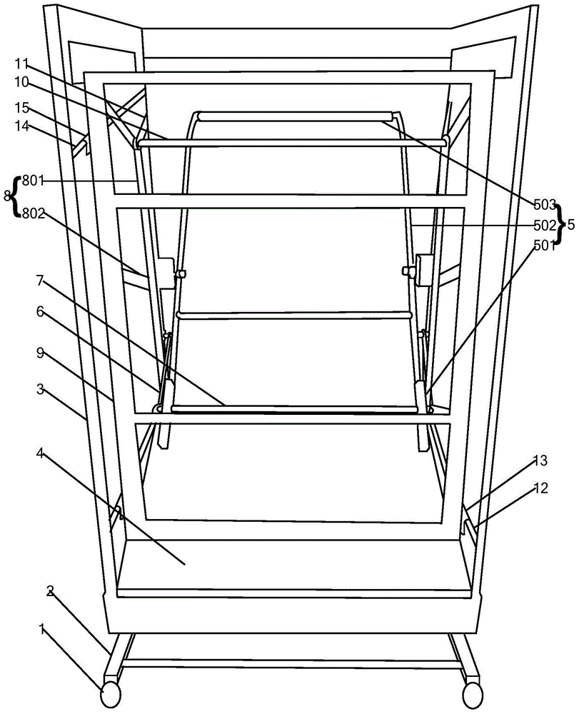
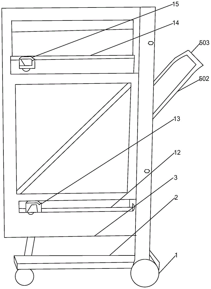
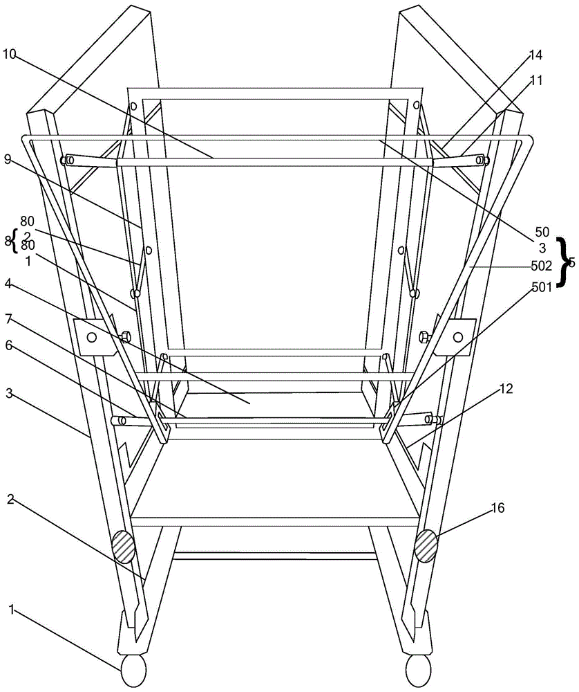
[0027] Please refer to the attached figure 1 , which shows the structure of a pushing mechanism shown in an exemplary embodiment of the present invention. The push mechanism shown in the embodiment of the present invention includes a roller 1, a support platform 2, tw...


PUM


Abstract

The invention discloses a push mechanism which comprises idler wheels, a supporting table, two side supporting pieces arranged on the supporting table and a front-end push platform arranged between the two side supporting pieces and further comprises a rear-end driving swing rod, two driven swing rods, a transverse connecting rod, linkage mechanisms and a push frame. The rear-end driving swing rod is connected with the side supporting pieces through hinges and limiting holes used for limiting the transverse connecting rod are formed in the bottom end of the rear-end driving swing rod. One end of each driven swing rod is correspondingly connected with the corresponding side supporting piece through a hinge and the other ends of the two driven swing rods are correspondingly connected with the two ends of the transverse connecting rod to fix the transverse connecting rod. The transverse connecting rod penetrates through the limiting holes of the rear-end driving swing rod and is connected with the linkage mechanisms. The linkage mechanisms are connected with the push frame and used for driving the push frame to move forwards and backwards in the front-end push platform. The rear-end driving swing rod is used for prying the transverse connecting rod penetrating through the limiting holes so as to drive the linkage mechanisms connected with the transverse connecting rod to drive the push frame to move forwards and backwards. By the adoption of the technical scheme, the push efficiency of raw materials can be improved.

Description

technical field [0001] The present invention relates to the technical field of packaging, and more specifically relates to a pushing mechanism. Background technique [0002] At present, with the rapid development of the packaging industry, the packaging of raw materials such as tobacco leaves also requires higher and higher processing efficiency. In related technologies, when pushing the raw materials to be packed into the packing machine for packing into bundles, it is often necessary to manually push very heavy raw materials into the packing machine to realize the packing of the raw materials into bundles. This manual push method is clumsy, slow, and inefficient, which leads to time-consuming and laborious packaging of raw materials. In addition, during the process of manually hugging raw materials and placing them in the baler, human factors may cause raw materials to loosen, waste more, Destroying the flatness of raw materials will eventually further make the packaging ...

Claims


Application Information

Patent Timeline
Patent Type & Authority Patents(China)
IPC IPC(8): B65B37/00
CPCB65B37/00
Inventor 谭友强黄国强罗安乐唐波
Owner 长沙金属狂潮农用机械科技有限公司
Why Eureka
Try Eureka