
Coiled material hoisting mechanism

A coiled material and sleeve technology, applied in the direction of load hanging components, transportation and packaging, can solve the problems of high labor intensity, low efficiency, inconvenient overturning or lifting mechanism connection, etc., so as to reduce labor intensity and improve work efficiency. The effect of efficiency

Active Publication Date: 2015-06-24
博斯特智能科技(张家港)有限公司
View PDF8 Cites 15 Cited by
  • Summary
  • Abstract
  • Description
  • Claims
  • Application Information

AI Technical Summary

Problems solved by technology

[0002] Due to the particularity of the shape of the coiled material product, the outer peripheral surface of the coiled material product is generally a material layer, which is inconvenient to directly connect with the turning or lifting mechanism, and the interior of the coiled material product is generally a smooth cylindrical wall surface, so it is also very difficult Difficult to connect effectively with existing clamping structures
At present, operations such as flipping or lifting coiled products are generally done manually. For example, when flipping coiled products, two or more people are often required to operate, so the labor intensity is high and the efficiency is low.

Method used


Image

  • Coiled material hoisting mechanism
  • Coiled material hoisting mechanism
  • Coiled material hoisting mechanism

Examples


Embodiment Construction

[0017] The present invention will be further described below in conjunction with the accompanying drawings and specific embodiments.

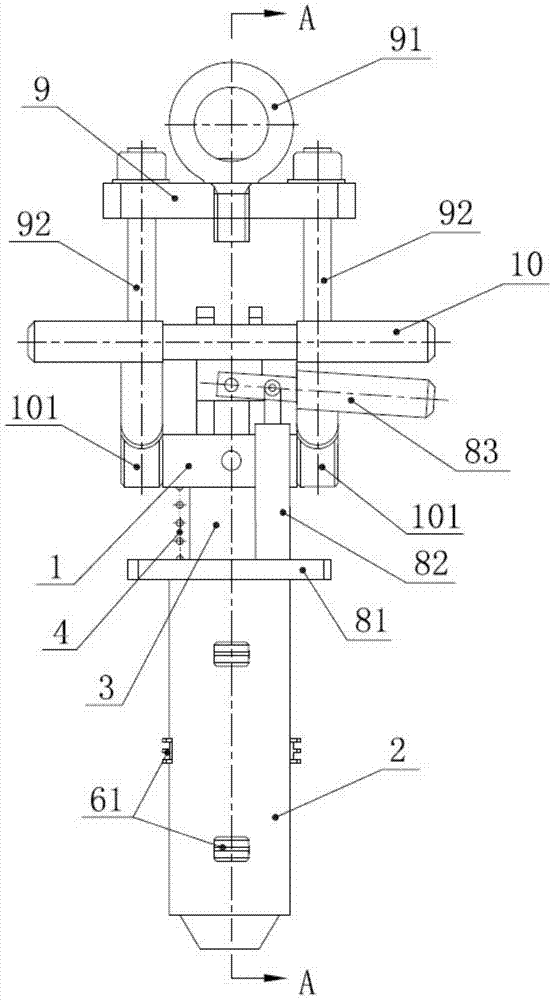
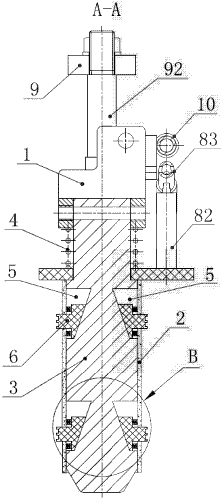
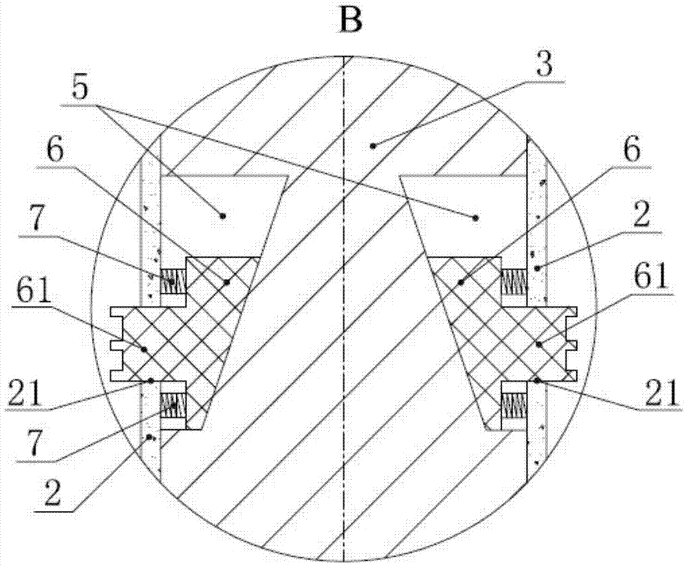
[0018] Such as Figure 1 to Figure 3 As shown in , the coil lifting mechanism of the present invention includes a mounting frame 1, a sleeve 2 and a valve core 3 located in the sleeve and capable of moving axially along the sleeve, the upper end of which passes through The sleeve is connected to the installation frame behind, and a sleeve return spring 4 is arranged between the upper end of the sleeve and the installation frame 1; at least one set of slope chute groups is provided on the outer peripheral surface of the valve core located in the sleeve 2, The slope chute group includes two mirror-image-symmetrically distributed slope chute 5, and a slope surface inclined relative to the axis of the valve core is arranged in the slope chute 5, and between each slope chute 5 and the sleeve 2 A slider 6 is provided on which a mating surface that c...


PUM


Abstract

The invention discloses a coiled material hoisting mechanism for overturning and hoisting a coiled material product, which can improve the working efficiency and alleviate the labor intensity of the operation personnel. The coiled material hoisting mechanism comprises an installation frame, a sleeve and a valve core which is arranged in the sleeve and can move along the axial direction of the sleeve, wherein at least one group of slope slide grooves is formed in the outer circumferential surface of the valve core in the sleeve, each group of slope slide grooves comprises two slope slide grooves which are distributed in a mirror symmetry manner, a slide block is arranged between each slope slide groove and the sleeve, a protrusion end block is arranged at one side, facing the wall of the sleeve, of each slide block, and the protrusion end block is movably inserted into a telescopic hole which is arranged on a corresponding position of the sleeve and allows the passing of the protrusion end block. The slide block can be driven to be unfolded and folded by virtue of the relative movement of the sleeve and the valve core, so that the coiled material hoisting mechanism can be tightly clamped in an inner through hole of the coiled material product; finally the coiled material product can be conveniently overturned or hoisted.

Description

technical field [0001] The invention relates to a coil lifting mechanism suitable for turning and lifting coil products. Background technique [0002] Due to the particularity of the shape of the coiled material product, the outer peripheral surface of the coiled material product is generally a material layer, which is inconvenient to be directly connected with the turning or lifting mechanism, and the interior of the coiled material product is generally a smooth cylindrical wall surface, so it is also very difficult It is difficult to effectively connect with the existing clamping structure. At present, operations such as flipping or lifting of coiled products are generally done manually. For example, when flipping coiled products, two or more people are often required to operate, so the labor intensity is high and the efficiency is low. Contents of the invention [0003] The technical problem solved by the present invention is to provide a coil lifting mechanism suitabl...

Claims


Application Information

Patent Timeline
Patent Type & Authority Applications(China)
IPC IPC(8): B66C1/56
CPCB66C1/56
Inventor 朱强孙光大杨发花
Owner 博斯特智能科技(张家港)有限公司
Learn More