
Hydraulic interlocking control loop

A hydraulic circuit and control circuit technology, applied in fluid pressure actuation devices, fluid pressure actuation system safety, servo motors, etc., can solve problems such as increasing the number of hidden dangers of oil leakage points, reducing circuit reliability, and increasing manufacturing costs. Achieve the effects of reducing the number of hidden dangers at oil spill points, increasing reliability, and saving manufacturing costs

Active Publication Date: 2015-06-24
CHONGQING UNIV OF POSTS & TELECOMM
View PDF6 Cites 2 Cited by
  • Summary
  • Abstract
  • Description
  • Claims
  • Application Information

AI Technical Summary

Problems solved by technology

[0006] This kind of hydraulic circuit mainly has the following problems: it is necessary to use electrical interlock to ensure the action requirements of the hydraulic circuit, and the risk of control increases. Personal injury; In addition, because two reversing valves are required in this circuit to control the hydraulic locks in their respective circuits, it not only increases the manufacturing cost, but also increases the number of hidden dangers of oil leakage points, thereby reducing the reliability of the circuit

Method used


Image

  • Hydraulic interlocking control loop
  • Hydraulic interlocking control loop

Examples


Embodiment Construction

[0014] The preferred embodiments of the present invention will be described in detail below with reference to the accompanying drawings.

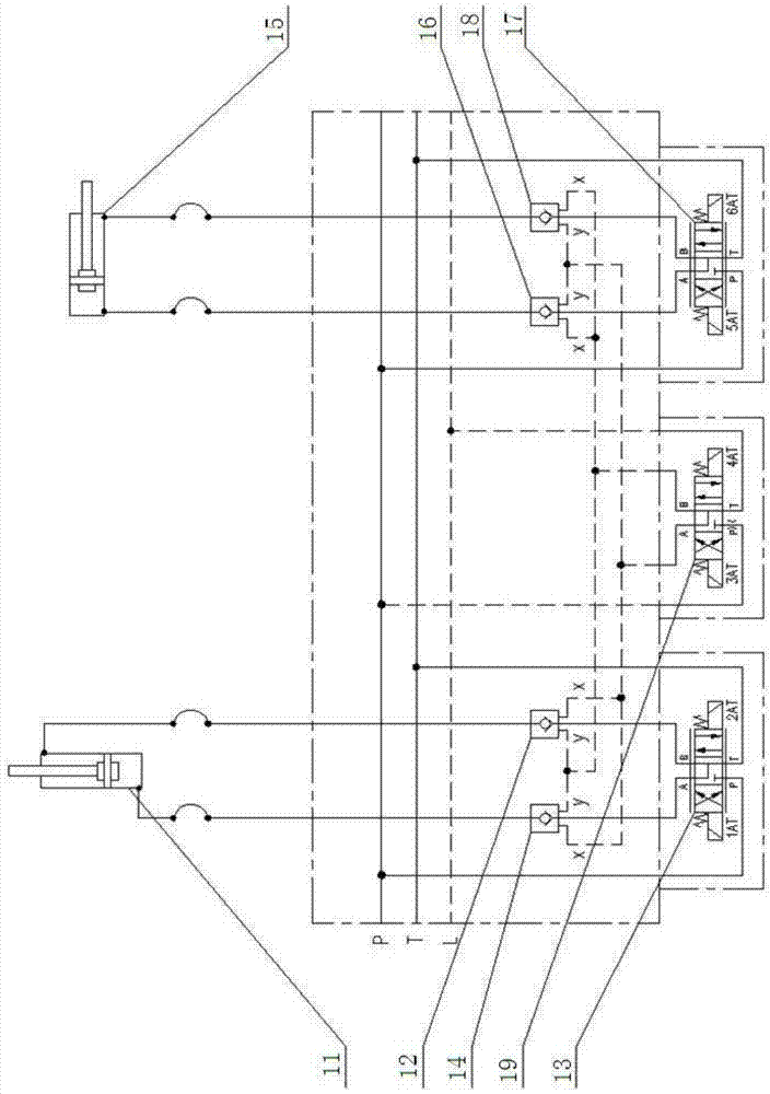
[0015] Such as figure 2 As shown, the hydraulic interlock control circuit in this embodiment includes a first hydraulic circuit and a second hydraulic circuit. The first hydraulic circuit is mainly connected by an oil cylinder I11, a hydraulic lock Ia12, a reversing valve I13 and a hydraulic lock Ib14. The second hydraulic circuit is mainly composed of oil cylinder II15, hydraulic lock IIa16, reversing valve II17 and hydraulic lock IIb18, and also includes reversing valve III19 for simultaneously controlling the hydraulic locks in the first and second hydraulic circuits , the left oil outlet A of the reversing valve III19 is connected in parallel with the control oil ports x of the hydraulic locks Ia12 and Ib14 in the first hydraulic circuit and the leakage oil ports y of the hydraulic locks IIa16 and IIb18 in the second hydraulic circuit....


PUM


Abstract

The invention discloses a hydraulic interlocking control loop which comprises a first hydraulic loop, a second hydraulic loop and a reversing valve III for simultaneously controlling hydraulic locks in the first hydraulic loop and the second hydraulic loop. A left oil outlet A of the reversing valve III is connected with control oil ports x of the hydraulic lock Ia and the hydraulic lock Ib in the first hydraulic loop and leakage oil ports y of the hydraulic lock IIa and the hydraulic lock IIb in the second hydraulic loop, and a right oil outlet B of the reversing valve III is connected with leakage oil ports y of the hydraulic lock Ia and the hydraulic lock Ib in the first hydraulic loop and control oil ports x of the hydraulic lock IIa and the hydraulic lock IIb in the second hydraulic loop. The interlocking function of the two hydraulic loops is achieved through a set of reversing valves, the problems of equipment damage and even personal injuries caused by electrical interlocking failure are effectively solved, and control risks are reduced. The number of the reversing valves needed in the loops is reduced, manufacturing cost is saved, the number of hidden troubles of oil leakage points is reduced, and the reliability of a system is improved.

Description

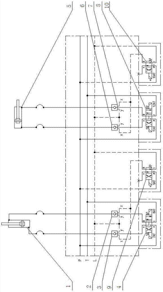
technical field [0001] The invention belongs to the field of hydraulic circuits, and in particular relates to a hydraulic control circuit with an interlock function. Background technique [0002] When the two mechanisms of the mechanical equipment cannot operate at the same time, they need to be realized through the interlock function. The existing interlock functions are mostly controlled by electricity. Even if the two mechanisms are controlled by hydraulic circuits, the interlock function is still controlled by electricity. Valve way to achieve. [0003] The hydraulic circuit control principle commonly used in the prior art is as follows: figure 1 As shown: oil cylinder 1 is connected with hydraulic locks 2, 3 and reversing valve 4, and oil cylinder 5 is connected with hydraulic locks 6, 7 and reversing valve 8. In order to realize the interlock function, reversing valve 9 and reversing valve are also provided in the control circuit. A reversing valve 10, wherein the re...

Claims


Application Information

Patent Timeline
Patent Type & Authority Applications(China)
IPC IPC(8): F15B11/16F15B13/06F15B20/00
CPCF15B11/16F15B13/06F15B20/00
Inventor 赵双袁威罗蓉萧红邱宝梅
Owner CHONGQING UNIV OF POSTS & TELECOMM
Learn More