Boiler pipe dirt cleaner

A technology for cleaning devices and pipelines, which is applied in the direction of cleaning heat transfer devices, flushing, lighting and heating equipment, etc., to achieve the effect of improving the flushing effect and widening the market prospect

Inactive Publication Date: 2015-06-24
李爽
0 Cites 0 Cited by

AI-Extracted Technical Summary

Problems solved by technology

[0006] The purpose of the present invention is to effectively solve the problem...

Abstract

A boiler pipe dirt cleaner is characterized by comprising an air pump, a pressure converter, a vortex generator, a water injection pipe, an agent injection pipe, a water outgoing pipe, an air injection pipe, a mix pipe and a housing; the air pump is connected with the air injection pipe; the water injection pipe and the air injection pipe are connected and are connected with the mix pipe; the agent injection pipe is connected with the mix pipe; the outlet end of the mix pipe is connected with one end of the vortex generator; the other end of the vortex generator is connected with the water outgoing pipe; the water injection pipe, the agent injection pipe, the water outgoing pipe and the air injection pipe all penetrate the housing and are fixed to the sidewall of the housing. The boiler pipe dirt cleaner has the advantages that the traditional single water cleaning mode is changed, the boiler heating pipe is cleaned with agent-carrying pulsating water, cleaning effect is greatly improved, water and electricity are saved, and the boiler pipe dirt cleaner has promising market prospect.

Application Domain

Technology Topic

Image

  • Boiler pipe dirt cleaner

Examples

  • Experimental program(3)

Example Embodiment

[0019] Example 1
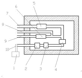
[0020] The invention provides a boiler pipe dirt cleaning device, which is characterized in that: the boiler pipe dirt cleaning device includes an air pump 1, a gas pressure converter 4, a vortex generator 6, a water injection pipe 7, an agent injection pipe 8, and a water outlet pipe 9 , gas injection pipe 10, mixture pipe 11, shell 12;
[0021] The air pump 1 is connected to the gas injection pipe 10, the water injection pipe 7 is connected to the mixture pipe 11 after joining the gas injection pipe 10, the injection pipe 8 is connected to the mixture pipe 11, the outlet end of the mixture pipe 11 is connected to one end of the vortex generator 6, and the vortex is generated The other end of the device 6 is connected to the water outlet pipe 9, and the water injection pipe 7, the agent injection pipe 8, the water outlet pipe 9 and the gas injection pipe 10 all pass through the shell 12 and are fixed on the side wall of the shell 12.
[0022] The boiler pipeline dirt cleaning device also includes a check valve 2 and a solenoid valve 3, and the check valve 2 and the solenoid valve 3 are installed on the gas injection pipe 10 in sequence.
[0023] The boiler pipe dirt cleaning device also includes a check valve 2 5 installed on the water injection pipe 7 .
[0024] In the boiler pipeline dirt cleaning device according to the present invention, the air passes through the air pump 1, the check valve 2, the solenoid valve 3 and the air pressure converter 4, and then mixes with water and the injected medicine, and then passes through the vortex generator 6 to form a The pulsating water flow of the agent is injected into the boiler heating pipe to be cleaned through the water outlet pipe 9 to effectively clean the boiler heating pipe.
[0025]

Example Embodiment

[0026] Example 2
[0027] The invention provides a boiler pipe dirt cleaning device, which is characterized in that: the boiler pipe dirt cleaning device includes an air pump 1, a gas pressure converter 4, a vortex generator 6, a water injection pipe 7, an agent injection pipe 8, and a water outlet pipe 9 , gas injection pipe 10, mixture pipe 11, shell 12;
[0028] The air pump 1 is connected to the gas injection pipe 10, the water injection pipe 7 is connected to the mixture pipe 11 after joining the gas injection pipe 10, the injection pipe 8 is connected to the mixture pipe 11, the outlet end of the mixture pipe 11 is connected to one end of the vortex generator 6, and the vortex is generated The other end of the device 6 is connected to the water outlet pipe 9, and the water injection pipe 7, the agent injection pipe 8, the water outlet pipe 9 and the gas injection pipe 10 all pass through the shell 12 and are fixed on the side wall of the shell 12.
[0029] The boiler pipe dirt cleaning device also includes a check valve 2 5 installed on the water injection pipe 7 .
[0030] In the boiler pipe dirt cleaning device of the present invention, the air passes through the air pump 1 and the air pressure converter 4 and then mixes with water and injected medicine, then passes through the vortex generator 6 to form a pulsating water flow with medicine, and injects it through the outlet pipe 9 The boiler heating pipes to be cleaned can effectively clean the boiler heating pipes.
[0031]

Example Embodiment

[0032] Example 3
[0033] The invention provides a boiler pipe dirt cleaning device, which is characterized in that: the boiler pipe dirt cleaning device includes an air pump 1, a gas pressure converter 4, a vortex generator 6, a water injection pipe 7, an agent injection pipe 8, and a water outlet pipe 9 , gas injection pipe 10, mixture pipe 11, shell 12;
[0034] The air pump 1 is connected to the gas injection pipe 10, the water injection pipe 7 is connected to the mixture pipe 11 after joining the gas injection pipe 10, the injection pipe 8 is connected to the mixture pipe 11, the outlet end of the mixture pipe 11 is connected to one end of the vortex generator 6, and the vortex is generated The other end of the device 6 is connected to the water outlet pipe 9, and the water injection pipe 7, the agent injection pipe 8, the water outlet pipe 9 and the gas injection pipe 10 all pass through the shell 12 and are fixed on the side wall of the shell 12.
[0035] The boiler pipeline dirt cleaning device also includes a check valve 2 and a solenoid valve 3, and the check valve 2 and the solenoid valve 3 are installed on the gas injection pipe 10 in sequence.

PUM

no PUM

Description & Claims & Application Information

We can also present the details of the Description, Claims and Application information to help users get a comprehensive understanding of the technical details of the patent, such as background art, summary of invention, brief description of drawings, description of embodiments, and other original content. On the other hand, users can also determine the specific scope of protection of the technology through the list of claims; as well as understand the changes in the life cycle of the technology with the presentation of the patent timeline. Login to view more.

Similar technology patents

Classification and recommendation of technical efficacy words

  • Improve flushing effect
  • Broad market prospect

People also interested in

Why Eureka
Try Eureka