Unlock instant, AI-driven research and patent intelligence for your innovation.
Processing box and image forming device matched with processing box
What is Al technical title?
Al technical title is built by PatSnap Al team. It summarizes the technical point description of the patent document.
A technology for processing boxes and images, which is applied in the fields of electrical recording technology using charge graphics, equipment for using electrical recording technology using charge graphics, and electrical recording technology, and can solve problems such as inability to identify features of image forming devices
Active Publication Date: 2015-06-24
NINESTAR CORP
View PDF13 Cites 12 Cited by
Summary
Abstract
Description
Claims
Application Information
AI Technical Summary
This helps you quickly interpret patents by identifying the three key elements:
Problems solved by technology
Method used
Benefits of technology
Problems solved by technology
[0004] The invention provides a process box to solve the technical problem that the existing process box cannot be used for feature recognition by the image forming device when it is installed in the image forming device to ensure that the drive head in the process box is driven to rotate after it is correctly installed in the image forming device
Method used
Image
Click on the blue label to locate the original text in one second.
Reading with bidirectional positioning of images and text.
Examples
Embodiment 1
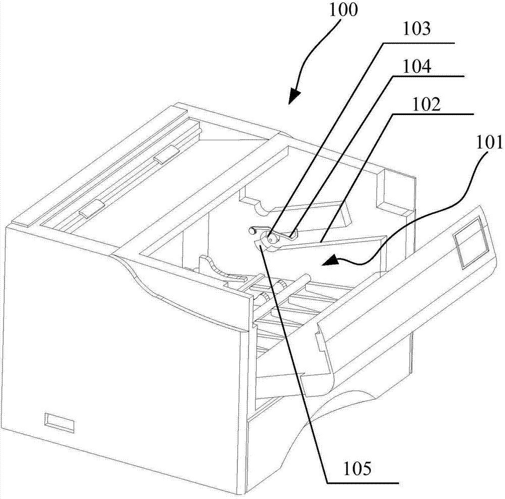
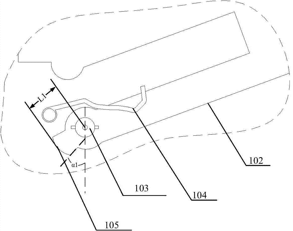
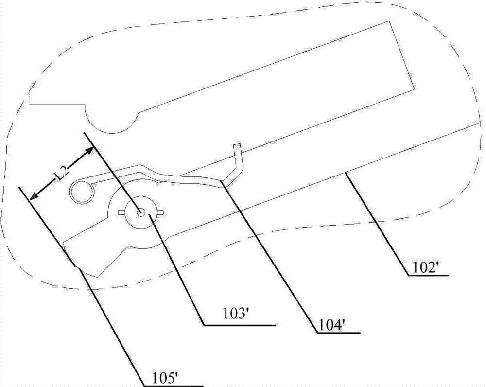
[0039] Such as figure 1 , Figure 2a-2c , image 3 As shown, preferably, the present embodiment 1 provides an image forming apparatus 100 comprising a process cartridge installation unit 101 configured to allow the process cartridge 1 (described in detail below) to be detachably installed therein; the drive mechanism is provided There is a motor, and the drive end 103, 103', 103 "connected with the motor, the drive end 103, 103', 103 "can drive the drive head 130 installed on the process box 1 in the image forming device 100 to rotate; guide rails 102, 102 ', 102" are arranged so that the process box 1 can be installed to a predetermined position along the predetermined track on the guide rail 102, 102', 102"; In the space defined by the guide rails 102, 102', 102", the dimensional relationship between the front ends 105, 105', 105" of the guide rails 102, 102', 102" and the driving ends 103, 103', 103" determines the size of the image forming apparatus 100. type. (The refe...
Embodiment 2
[0051] Such as Figures 6a-6c As shown, preferably, the difference between the image forming apparatus provided by the second embodiment and the first embodiment is that sensors 206, 206', 206", the sensor can be a travel switch, a position sensor, or a light sensor. Other features are the same as in the first embodiment.
[0052] Such as Figure 7 , Figure 8a As shown, preferably, the difference between the process cartridge 2 provided in Embodiment 2 and the process cartridge 1 provided in Embodiment 1 is that, in order to simplify the structure, the drive head 23 is directly connected to one end of the photosensitive element 24, and the drive head 23 The axis Y2 is inclined to the axis Y1 of the photosensitive element 24 in the natural state, while in the coupled state, Y2 is coaxial with Y1. And both sides of the process box 2 are also provided with positioning posts, these positioning posts are arranged on both sides of the process box, during the installation process...
PUM
Abstract
The invention relates to a processing box and an image forming device matched with the processing box. The processing box comprises photosensitive elements, developing elements, a first framework used for holding the developing elements, a second framework used for holding the photosensitive elements, driving heads used for receiving driving force from the image forming device and driving the photosensitive elements or the developing elements to rotate, and characteristic identification parts which are arranged in front of the driving heads in the mounting direction of the processing box and are used for characterizing characteristics of the processing box. The image forming device also comprises a characteristic recognition part used for detecting the characteristic identification parts and recognizing the characteristics of the processing box. According to the processing box and the image forming device matched with the processing box, the driving end of the image forming device is capable of driving the driving heads in the processing box to work only when the processing box is installed in the right image forming device, so that the technical problem that the condition that the driving heads in the processing box can be driven to rotate after the process box is installed in the right image forming box cannot be ensured as the image forming device is incapable of recognizing the characteristics when the existing processing box is installed in the image forming device.
Description
technical field [0001] The invention relates to the technical field of electrophotography, in particular to a process box and an image forming device matched with it. Background technique [0002] With the maturity of electrophotographic technology, electrophotographic image forming devices have been well developed in the office printing market due to their high speed and low printing cost. The image forming device in the prior art is generally provided with a process box detachably installed therein, and this process box is usually provided with a photosensitive element and a developing element; one end of the photosensitive element is usually provided with a drive head, which can receive the The driving force of the driving mechanism in the image forming device, which can drive the photosensitive element to rotate, and the printing medium is arranged under the photosensitive element; The element forms a predetermined thickness of the developer; after the photosensitive el...
Claims
Application Information
Patent Timeline
Application Date:The date an application was filed.
Publication Date:The date a patent or application was officially published.
First Publication Date:The earliest publication date of a patent with the same application number.
Issue Date:Publication date of the patent grant document.
PCT Entry Date:The Entry date of PCT National Phase.
Estimated Expiry Date:The statutory expiry date of a patent right according to the Patent Law, and it is the longest term of protection that the patent right can achieve without the termination of the patent right due to other reasons(Term extension factor has been taken into account ).
Invalid Date:Actual expiry date is based on effective date or publication date of legal transaction data of invalid patent.
