Shifting register, grid drive circuit, display device and grid drive method

A technology of shift register and gate drive, which is applied in the field of gate drive circuit, gate drive, and shift register, and can solve the problems of large number of thin film transistors and large occupied space

Inactive Publication Date: 2015-06-24
BOE TECH GRP CO LTD +1
View PDF7 Cites 50 Cited by
  • Summary
  • Abstract
  • Description
  • Claims
  • Application Information

AI Technical Summary

Problems solved by technology

But there are also certain problems in the design of the existing GOA circuit, such as figure 1 As shown, the number of thin film transistors (TFTs) in each shift register in the existing GOA circuit is relatively large (ie, M1-M6 ~ M8-M11), and each shift register can only be used to drive a row of gates line, so it takes up a lot of space, so further reducing the space occupied by the GOA circuit can realize the narrow bezel design in the true sense

Method used


Image

  • Shifting register, grid drive circuit, display device and grid drive method
  • Shifting register, grid drive circuit, display device and grid drive method
  • Shifting register, grid drive circuit, display device and grid drive method

Examples


Embodiment 1

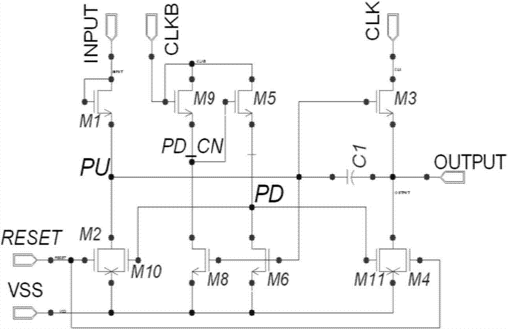
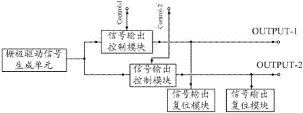
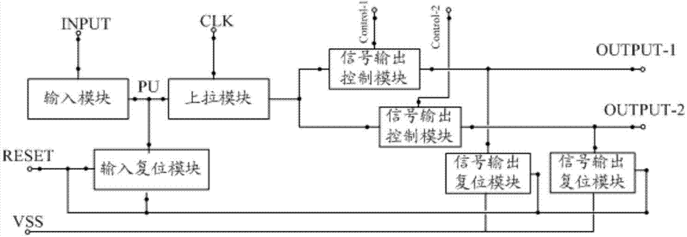
[0061] combine image 3 As shown, this embodiment provides a shift register, wherein the gate drive signal generating unit of this embodiment includes: an input module, a pull-up module, an input reset module, and multiple signal output control modules and multiple signal output reset modules. module. Among them, the input module is connected to the signal input terminal INPUT, the reset module and the pull-up control node PU, and is used to control the potential of the pull-up control node PU according to the signal input from the signal input terminal INPUT. The pull-up control node PU is the input module and the pull-up control node PU. The connection point of the module; the pull-up module is connected to the pull-up control node PU, the first clock signal input terminal CLK and each signal output control module, and is used for inputting according to the potential of the pull-up control node PU and the first clock signal input terminal CLK The control of the first clock ...


PUM


Abstract

The invention provides a shifting register, a grid drive circuit, a display device and a grid drive method. The problem that the ultra-low width design of a frame of a display device is limited by an existing shifting register can be solved. The shifting register comprises a grid drive signal generating unit for outputting grid drive signals, a plurality of signal output control modules, signal output reset modules and signal output ends. Each signal output control module is connected with the grid drive signal generating unit, a corresponding control signal input end and the corresponding signal output end. Each signal output reset module is connected between the corresponding signal output control module and the corresponding signal output end. Each signal output control module is used for outputting the grid drive signals output by the grid drive signal generating unit through the corresponding signal output end under the control of input control signals. Each signal output reset module is used for making output signals of the corresponding output end reset.

Description

technical field [0001] The invention belongs to the field of display technology, and in particular relates to a shift register, a gate drive circuit, a display device and a gate drive method. Background technique [0002] The basic principle of TFT-LCD (Thin Film Transistor-Liquid Crystal Display, thin film transistor liquid crystal display) to realize a frame display is to input a square wave of a certain width to each row of pixels sequentially from top to bottom through the gate drive. strobe, and then through the source (source) to drive the signal required for each row of pixels to be output from top to bottom in turn. At present, the display device with such a structure is usually made of gate drive circuit and source drive circuit on the glass panel by COF (Chip On Film, chip-on-film) or COG (Chip On Glass, chip directly fixed on the glass) process. However, when the resolution is high, the output of the gate drive circuit and the source drive circuit will increase, ...

Claims


Application Information

Patent Timeline
Patent Type & Authority Applications(China)
IPC IPC(8): G09G3/36G11C19/28
CPCG09G3/3677G09G2310/0286G09G2310/08G11C19/28G09G3/3648G09G2300/0426G09G2320/0209
Inventor 陈华斌封宾袁剑峰
Owner BOE TECH GRP CO LTD
Why Eureka
Try Eureka