Systems and methods for robotic surgery

A technique of surgery and surgical instruments, applied in the field of surgical manipulators, which can solve problems such as collision and undesired

Active Publication Date: 2015-06-24
STRYKER CORP
View PDF14 Cites 41 Cited by
  • Summary
  • Abstract
  • Description
  • Claims
  • Application Information

AI Technical Summary

Problems solved by technology

However, there may be situations where after the procedure has begun it becomes apparent that the instrument may collide with a target at the surgical site and such contact is undesirable

Method used


Image

  • Systems and methods for robotic surgery
  • Systems and methods for robotic surgery
  • Systems and methods for robotic surgery

Examples


Embodiment Construction

[0059] I. Overview

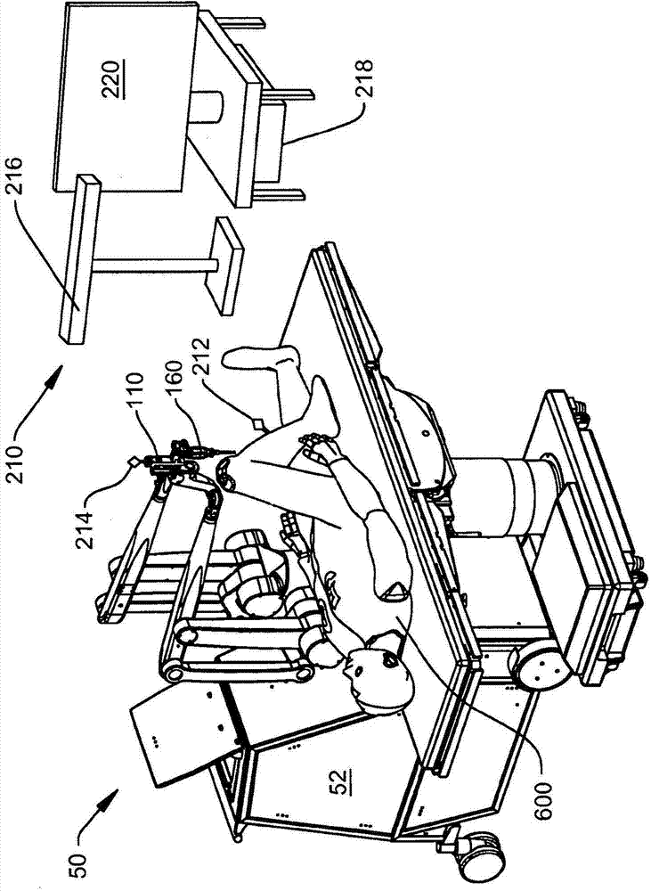
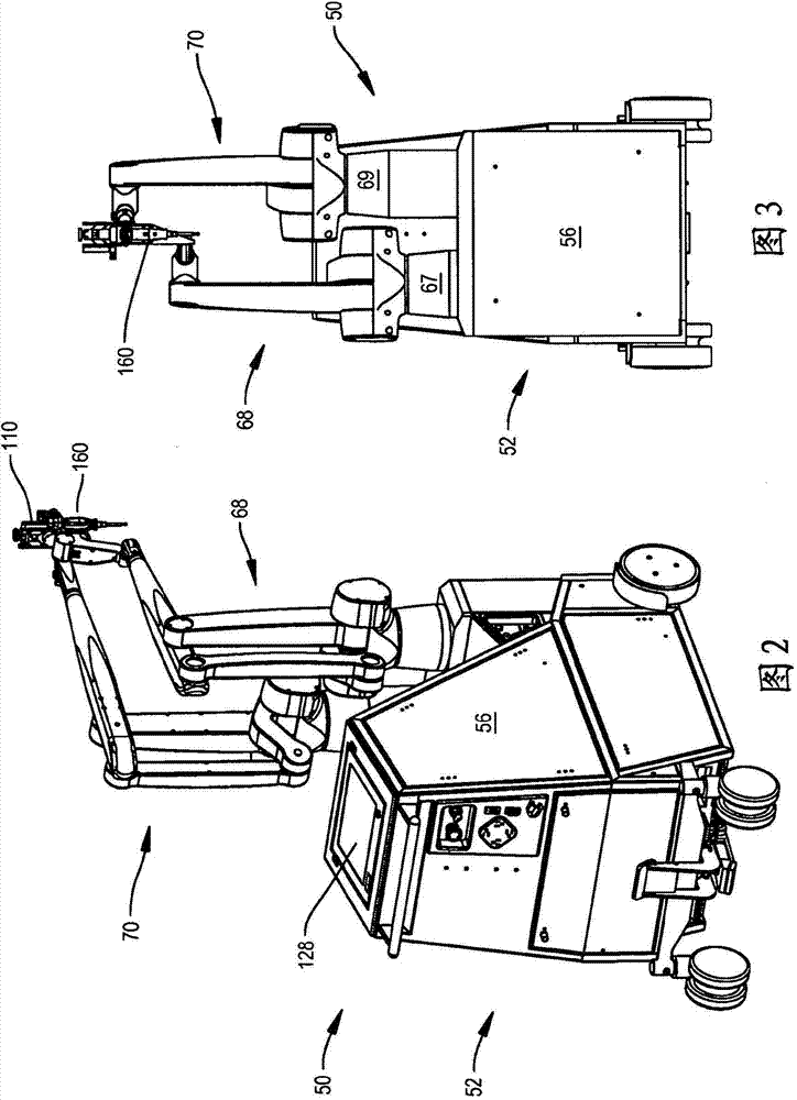
[0060] The present invention relates generally to new and usable surgical manipulators that position surgical instruments or tools in or on a patient. The surgical manipulator positions the surgical instrument so that the end of the instrument that will be applied to the tissue is only applied to the tissue to which the instrument should be applied.

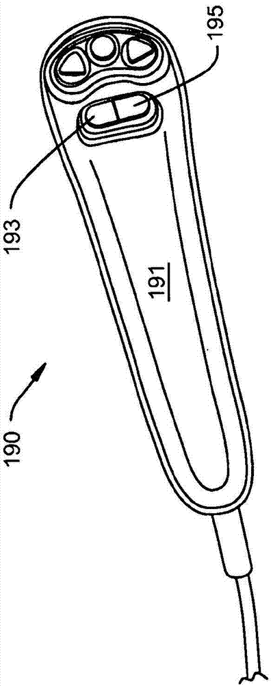
[0061] The manipulator can be operated in manual mode or semi-automatic mode. When the manipulator is operating in manual mode, the manipulator monitors the force and torque that the practitioner applies to the instrument to position the instrument. These forces and torques are measured by sensors, which are part of the manipulator. In response to the force and torque applied by the medical practitioner, the manipulator essentially moves the instrument in real time. Therefore, the movement of the instrument performed by the manipulator can be regarded as the movement of the instrument that simulates the desired...


PUM


Abstract

A surgical manipulator for manipulating a surgical instrument and an energy applicator extending from the surgical instrument. The surgical manipulator further includes at least one controller configured to determine a commanded pose to which the energy applicator is advanced, wherein the commanded pose is determined based on a summation of a plurality of force and torque signals.

Description

[0001] Cross reference of related applications [0002] This application claims the priority of U.S. Provisional Patent Application No. 61 / 679,258 filed on August 3, 2012 and U.S. Provisional Patent Application No. 61 / 792,251 filed on March 15, 2013, the rights and disclosures of these two applications The full content is incorporated by reference. Technical field [0003] The present invention relates generally to surgical manipulators. More specifically, the present invention relates to a surgical manipulator that can be operated in a manual or semi-automatic mode. Background technique [0004] Recently, medical practitioners have found it useful to use robotic devices to assist in surgical operations. The robotic device usually includes a movable arm that includes one or more coupling mechanisms. The arm has a free distal end, which can be placed with very high accuracy. A surgical instrument designed to be applied to the surgical site is attached to the free end of the arm. ...

Claims


Application Information

Patent Timeline
Patent Type & Authority Applications(China)
IPC IPC(8): A61B19/00A61B17/16
CPCA61B17/1604A61B17/1626A61B17/1655A61B17/1657A61B17/1659A61B17/1662A61B34/10A61B34/20A61B34/30A61B34/32A61B34/37A61B34/70A61B34/74A61B17/16A61B18/148A61B2018/00601A61B2018/00565A61B2034/2046A61B2034/2059A61B2034/2055A61B2034/2068A61B2034/107A61B2034/104Y10S901/09A61B2034/102A61B2090/064A61B2090/066A61B34/76B25J13/00B25J9/1633B25J9/161
Inventor D·G·鲍林J·M·斯图尔特J·A·卡尔普D·W·马拉克沃斯基J·L·莫克特苏马·德拉巴雷拉P·勒斯勒尔J·N·比尔J·凯琴尔
Owner STRYKER CORP
Why Eureka
Try Eureka