Vibrating Parts Conveyor

A conveying device and vibrating technology, which is applied in the field of vibrating component conveying devices, can solve the problems of lowering the natural vibration frequency, lowering the driving frequency, and increasing the mass of the abutment

Inactive Publication Date: 2016-08-24
NTN CORP
View PDF8 Cites 0 Cited by
  • Summary
  • Abstract
  • Description
  • Claims
  • Application Information

AI Technical Summary

Problems solved by technology

However, in this case, since not only the mass of the component transport member but also the base increases, the natural frequency of vibration in the same direction as the component transport direction, that is, the horizontal direction, decreases.
In addition, in order to efficiently obtain the vibration displacement in the horizontal direction that requires a large amplitude, the frequency (drive frequency) of the power supply voltage waveform applied to the electromagnet is set to a frequency near the natural frequency of the horizontal direction to generate Resonant vibration, so if the natural frequency in the horizontal direction is lowered, the driving frequency will also be lowered, resulting in slower parts conveying speed

Method used


Image

  • Vibrating Parts Conveyor
  • Vibrating Parts Conveyor
  • Vibrating Parts Conveyor

Examples


Embodiment Construction

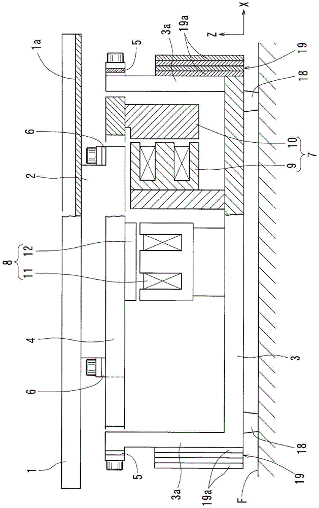
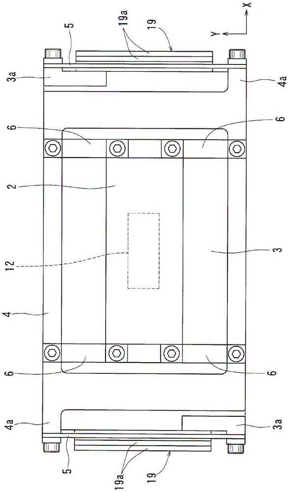
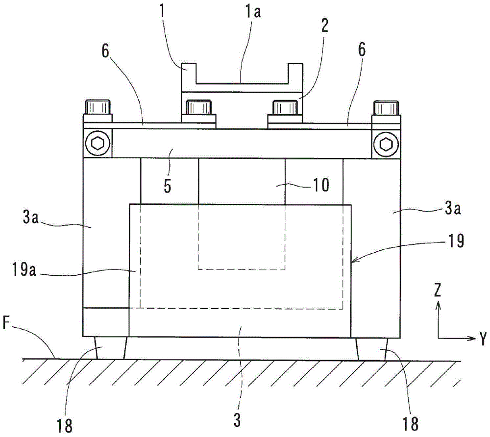
[0043] Embodiments of the present invention will be described below with reference to the drawings. Such as Figure 1 to Figure 3 As shown, in this vibratory component conveying device, a trough (part conveying member) 1 formed with a linear conveying path 1a is mounted on the upper surface of an upper vibrating body 2, and the upper vibrating body 2 and the ground An intermediate vibrating body 4 is arranged between the bases 3, and the intermediate vibrating body 4 is connected to the base 3 by two leaf springs 5 ​​as the first elastic members, and the upper part is vibrated by four leaf springs 6 as the second elastic members. The body 2 is connected with the intermediate vibrating body 4, and the first vibrating mechanism 7 that generates vibrations in the horizontal direction (parts conveying direction, X direction in the figure) is provided between the intermediate vibrating body 4 and the base 3, and the upper vibrating body 2 A second vibration excitation mechanism 8 ...


PUM


Abstract

A complex vibrating type parts transport device that can maintain the parts transport speed and suppress pitching motion of a parts transport member (1). After increasing the eigenfrequency of the rotational vibration (rotational vibration mode for vibration in the horizontal direction) generated in an intermediate vibrating body (4) and a base (3) to be greater than the eigenfrequency of a rotational vibration (rotational vibration mode for vibration in the vertical direction) generated in the parts transport member (1) and a upper vibrating body (2), the pitching motion of the parts transport member (1), viewed from the floor, can be suppressed and the parts transport speed can be maintained without a decrease in the eigenfrequency of a translational vibration mode for vibration in the horizontal direction by adjusting the mass of the base (3) so that the amplitude of the pitching motion (vibration level of the rotational vibration mode for vibration in the horizontal direction) of the base (3) is near the amplitude of the relative pitching motion (vibration level of the rotational vibration mode for vibration in the vertical direction) corresponding to the base (3) of the parts transport member (1).

Description

technical field [0001] The present invention relates to a vibrating component conveying device that vibrates a component conveying member by driving a vibration excitation mechanism to convey components. Background technique [0002] Among the vibratory component conveying devices, there is a compound vibrating component conveying device that aims to apply vibrations that are most suitable for conveying parts to the component conveying member, and is constructed so that the horizontal vibration in the vertical direction uses a leaf spring to vibrate the parts on the ground. The base installed on the top is connected to the intermediate vibrating body, and the component conveying member is connected to the intermediate vibrating body with a leaf spring for vertical vibration facing the horizontal direction, so that the horizontal vibration and the vertical vibration of the component conveying member can be adjusted separately. . [0003] However, in such a compound vibration...

Claims


Application Information

Patent Timeline
Patent Type & Authority Patents(China)
IPC IPC(8): B65G27/08B65G27/24
CPCB65G27/24B65G27/32
Inventor 石河智海
Owner NTN CORP
Why Eureka
Try Eureka