Wall rings for axial fans with wall ring heaters

An axial-flow, wall-ring technology, applied in the field of wall-ring, can solve the problem that the wall-ring heater is not energy-efficient, and achieve the effect of ensuring accurate positioning

Active Publication Date: 2017-07-04
EBM PAPST MULFINGEN GMBH & CO KG
View PDF4 Cites 0 Cited by
  • Summary
  • Abstract
  • Description
  • Claims
  • Application Information

AI Technical Summary

Problems solved by technology

Therefore, such a wall ring heater is not energy efficient

Method used


Image

  • Wall rings for axial fans with wall ring heaters
  • Wall rings for axial fans with wall ring heaters
  • Wall rings for axial fans with wall ring heaters

Examples


Embodiment Construction

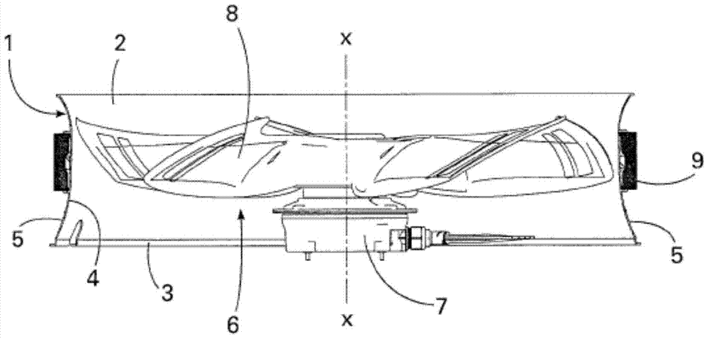
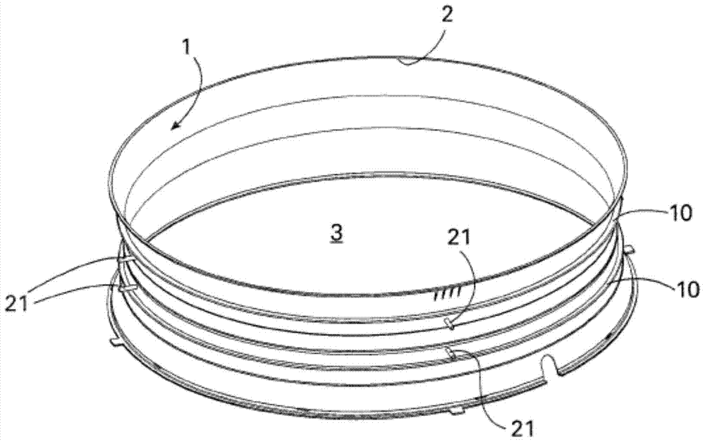
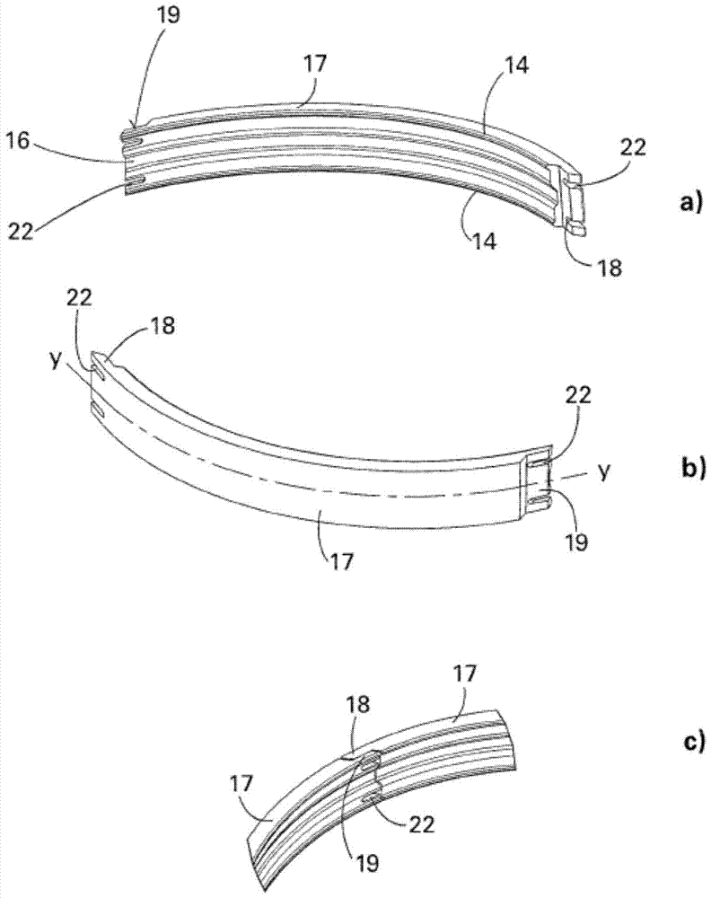
[0039] exist Figure 1~6 In , identical parts and functionally similar parts are always indicated by the same reference numerals. Although a certain feature of the wall ring according to the invention or already described elements and / or elements from the drawings are only described in coordination with each other in one embodiment, this feature is also necessary in the invention, irrespective of the embodiment described, A single feature or a combination of other features in an embodiment can be construed as the present invention.

[0040] As shown, a wall ring according to the invention comprises an annular body 1 with a central longitudinal axis X-X, which has a fluid inlet 2 and a fluid outlet 3 . The annular body 1 of the invention has a wall ring 4 located between two openings 2, 3 and has a circular cross-section perpendicular to the central axis X-X. In the embodiment shown, there is an axial fan 6 inside the wall ring. The axial fan 6 comprises an electric motor 7 ...


PUM


Abstract

The invention relates to a wall ring, in particular for receiving an axial fan (6), comprising in particular an annular body (1) with a central longitudinal axis (X‑X), a fluid inlet (2), a A fluid outlet (3), and an electrical heating means provided on at least some part of the circumference of the annular body (1). A profile covering part (9) made of a heat insulating material is movably fixed on the outer surface of some part of the circumference of the annular body (1), said profile covering part (9) and the annular body (1) together A receiving area is formed on the circular wall of the annular body to receive the electrical heating member.

Description

technical field [0001] The invention relates to a wall ring, in particular for receiving an axial fan, comprising an annular body with a central longitudinal axis, the annular body having a fluid inlet and a fluid outlet, in particular, said wall ring comprising An electrical heating member disposed on at least part of the circumference of the annular body. Background technique [0002] Axial fans are used, among others, for applications at low temperatures. At this point, there is a risk of ice forming and thus the fan blades will freeze on the wall ring. In typical applications this risk exists in heat pumps, evaporators in cold rooms, etc. In order to prevent occurrences such as freezing, it is a known procedure to mount heating elements in the form of electrical resistance heaters on the wall ring and use this as a heater. A disadvantage here is that a large amount of energy has to be supplied all the way to heat the wall ring in order to prevent the formation of ice ...

Claims


Application Information

Patent Timeline
Patent Type & Authority Patents(China)
IPC IPC(8): F04D19/00F04D29/52F04D29/58
CPCF04D19/002F04D29/522F04D29/584F04D29/5853F05B2260/231F05B2280/6012Y02T50/60F04D29/582F05D2260/231F05D2300/612
Inventor 迪特尔·贝斯特奥斯玛·斯特勒贝尔斯蒂芬妮·沃尔法特
Owner EBM PAPST MULFINGEN GMBH & CO KG
Why Eureka
Try Eureka