
Form rolling equipment and form rolling method

A technology of forming rolling and equipment, applied in the direction of metal rolling, other household appliances, household appliances, etc., can solve problems such as insufficient, and achieve the effect of improving accuracy

Inactive Publication Date: 2017-11-24
AISIN SEIKI KK
View PDF1 Cites 0 Cited by
  • Summary
  • Abstract
  • Description
  • Claims
  • Application Information

AI Technical Summary

Problems solved by technology

According to this method, a certain effect of eliminating the undulation of the tooth line is obtained, however, this effect is not sufficient

Method used


Image

  • Form rolling equipment and form rolling method
  • Form rolling equipment and form rolling method
  • Form rolling equipment and form rolling method

Examples


Embodiment Construction

[0035] One embodiment of a shape rolling apparatus and a shape rolling method will be explained below with reference to the description of the accompanying drawings.

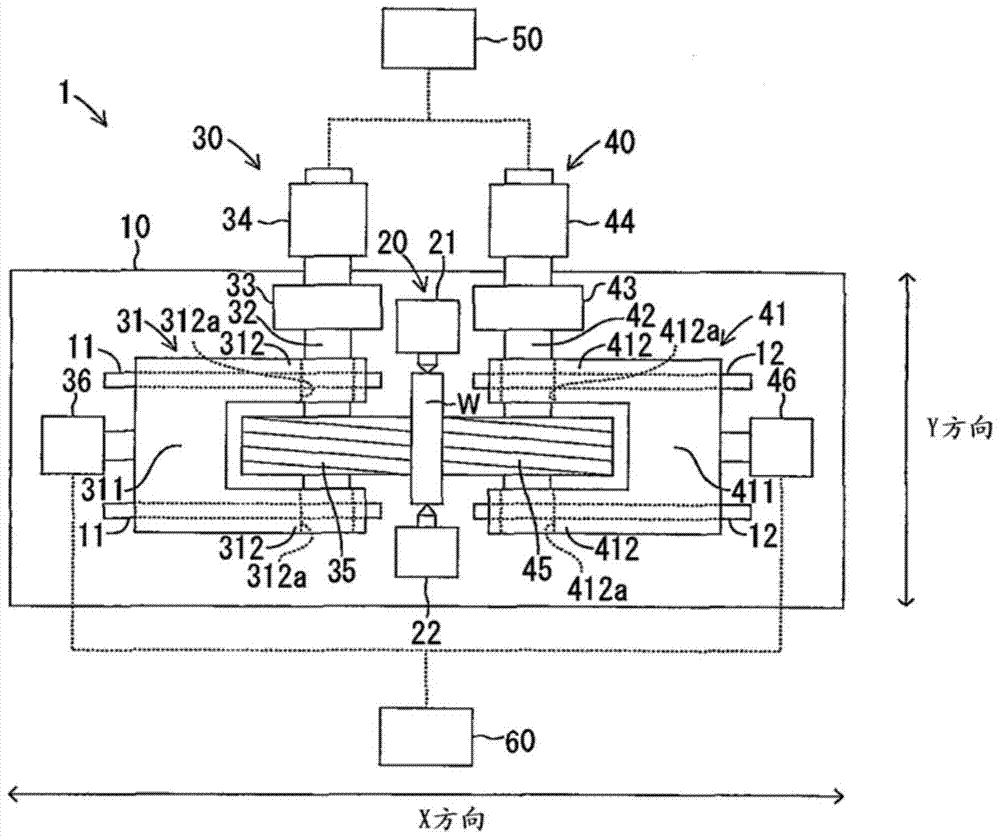
[0036] like figure 1 As shown in , the forming rolling apparatus 1 includes a base plate 10 , a support portion 20 , a first die unit 30 , a second die unit 40 , a rotation control device 50 and a position control device 60 .

[0037] like figure 1 As shown in , the substrate 10 is formed in a substantially rectangular shape in plan view. For purposes of explanation, the longitudinal direction of the substrate 10 (ie, figure 1 The left and right directions in the) are defined along the X direction, and the direction orthogonal to the X direction ( figure 1 The up and down direction in the ) is defined as the Y direction. The direction orthogonal to the X direction and the Y direction is the up and down direction.

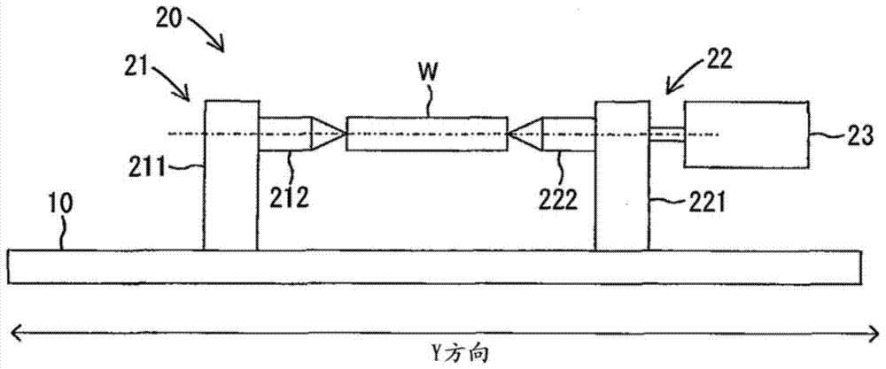
[0038] The support portion 20 is provided on the substrate 10 . The supporting part 20 inclu...


PUM


Abstract

A form rolling apparatus for applying in-feed form rolling to a rod-shaped material (W) includes a support portion (20) configured to support the rod-shaped material (W) to be axially rotatable, a round die (35, 45) formed with die teeth (T1, T2) on an outer periphery thereof, the die teeth (T1, T2) configured to be positioned facing an outer periphery surface of the rod-shaped material (W), and a moving device (36, 46) moving the round die (35, 45) so that a distance of axes of the round die (35, 45) and the rod-shaped material (W) changes. The die teeth (T1, T2) includes forming die teeth (T1) for generating gear teeth (T3) on the outer periphery surface of the rod-shaped material (W) and finishing die teeth (T2) enhancing a tooth surface precision of the generated gear teeth (T3) by engaging with the generated gear tooth (T3) and rotating. The finishing die teeth are formed in a configuration each having an addendum that does not come to contact a bottom land of the generated gear teeth (T3).

Description

technical field [0001] The present disclosure generally relates to form rolling apparatus and form rolling methods. Background technique [0002] Form rolling is a manufacturing method of rolling a shape on the outer peripheral surface of a rod-shaped material by driving a form-rolling die in a state where die teeth formed on the form-rolling die are pressed against the outer peripheral surface of the rod-shaped material. A manufacturing method in which deformation processing is applied. Usually, a rack die or a circular die is used as a forming rolling die. Form rolling is widely suitable for forming, for example, helical gears, screws, worms of reduced size, and splines because the manufacturing method is environmentally friendly, has high productivity, and has low manufacturing costs. [0003] Form rolling includes two types of manufacturing methods, in-feed form rolling and incremental rolling. According to cross-feed forming rolling, the die teeth of the forming roll...

Claims


Application Information

Patent Timeline
Patent Type & Authority Patents(China)
IPC IPC(8): B21H5/00
CPCB21H5/02B21H5/022Y10T29/49467B21B1/16B21B39/26
Inventor 永田英理
Owner AISIN SEIKI KK
Learn More