Spherical bogie

A bogie and ball-type technology, applied in the field of bogies, can solve problems such as roadway blockage, shuttle wheel derailment, center of gravity deviation, etc., to prevent derailment, solve friction problems, and facilitate disassembly and assembly

Inactive Publication Date: 2015-07-01
JIANGXI LANXIANG HEAVY IND
View PDF5 Cites 0 Cited by
  • Summary
  • Abstract
  • Description
  • Claims
  • Application Information

AI Technical Summary

Problems solved by technology

Traditional bogies (such as figure 1 , figure 2 (shown) is that a mandrel is set on the center plate on the bolster, and a bearing is set on the mandrel, and the mandrel is fixedly connected with the beam of the car body through a copper sleeve, a connecting plate, a sealing ring, etc., including the bogie with such a structure. The car body of the mine car can only rotate on the horizontal plane but cannot yaw or adjust the center of gravity, and there are many parts, which are easy to wear and often need to be replaced; because the center of gravity always deviates when the mine car is loaded (especially underground coal or gangue irregular shape, uneven loading, etc.), when the mine car is running on uneven or irregular tracks, it cannot automatically adjust the center of gravity, resulting in the four wheels of the mine car not being in good contact with the guide rails, and it is prone to shuttles. The phenomenon of wheel derailment
Once the track falls, the entire roadway will be blocked. It is necessary to manually remove all the gangue filled in the shuttle car, and then lift the shuttle car to the track surface. Especially in the case of a small roadway, the entire shuttle car must be disassembled. , otherwise it is difficult to solve the problem
This situation seriously affects the efficiency of mucking and transportation and the progress of engineering excavation, increases the cost of engineering excavation, has major safety hazards, and will damage equipment

Method used


Image

  • Spherical bogie
  • Spherical bogie
  • Spherical bogie

Examples


Embodiment Construction

[0012] In order to enable those skilled in the art to better understand the technical solutions of the present invention, the present invention will be further described in detail below in combination with specific implementations according to the accompanying drawings.

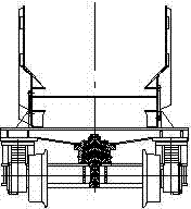
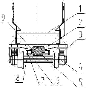
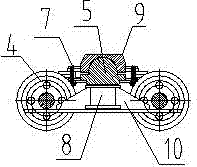
[0013] Such as image 3 , Figure 4 As shown, the spherical bogie is located at the lower part of the car body 1 of the rail-wheel type shuttle mine car, and it includes a wheel set 4, a symmetrically arranged side beam 10 connected to the wheel set, and generally passes through a guide between the side beam and the wheel set. Frames (not shown in the figure) are connected, a spring assembly 3 is provided, a bolster 8 is arranged between the side beams, and the bolster is perpendicular to the side beams at both ends, and a crossbeam 2 is arranged on the car body 1, and the width of the crossbeam is two The end gradually increases toward the middle position, the beam is provided with a spherical concave groov...


PUM


Abstract

The invention discloses a spherical bogie. The spherical bogie is located on the lower portion of a car body (1) of a rail wheel type shuttle mine car. The spherical bogie comprises a wheel set (4), side beams (10), a spring assembly (3) and a bottom bolster (8), wherein the side beams are symmetrically arranged and used for connecting the wheel set, the bottom bolster is arranged between the side beams, the car body is provided with a beam (2), a spherical groove (9) is formed in the beam, a spherical convex block (5) which is matched with the spherical groove (9) is arranged on the corresponding position of the bottom bolster, a lubricating oil passage is arranged between the spherical groove and the spherical convex block, support plates (6) are arranged on the spherical groove and the spherical convex block, and limit chains (7) are clamped between the support plates. By means of the spherical bogie, the center of gravity of the car body can be adjusted automatically, the lubricating oil passage is arranged, the problem o friction is effectively solved, the spherical groove is prevented from exceeding a limiting position by the limit chains arranged around the spherical bogie during 360-degree rotating of deflection, the spherical groove can controlled in a certain range, it is guaranteed that the shuttle car conducts normal transport work, and the phenomenon that the shuttle car falls from an uneven or irregular rail is prevented.

Description

technical field [0001] The invention relates to a bogie of a rail wheel shuttle mine car, in particular to a ball bogie. Background technique [0002] The rail-wheel shuttle mine car is a high-efficiency mucking transportation equipment commonly used in roadway excavation construction such as underground mines, railway tunnels, hydraulic culverts, and national defense underground projects. It plays the role of supporting the car body, steering and braking, and ensures that the shuttle car The vehicle runs safely and smoothly on the track. The principle of the rail-wheel shuttle mine car is through the upper and lower connection plates of the car box body, and is supported by two bogies for walking. Traditional bogies (such as figure 1 , figure 2 (shown) is that a mandrel is set on the center plate on the bolster, and a bearing is set on the mandrel, and the mandrel is fixedly connected with the beam of the car body through a copper sleeve, a connecting plate, a sealing r...

Claims


Application Information

Patent Timeline
Patent Type & Authority Applications(China)
IPC IPC(8): B61F5/16
CPCB61F5/16
Inventor 李杨贾忠翰刘明初陈振华唐福新刘艳李凯何萍许彪张红钢张健
Owner JIANGXI LANXIANG HEAVY IND
Why Eureka
Try Eureka