
Magnetic levitation automatic constant yarn leading tension roving serial suspension spindle

A technology of magnetic levitation and hanging spindle, which is applied to spinning machines, continuous winding spinning machines, textiles and paper making, etc., can solve the problems of increasing the operator's operating intensity, affecting the spinning quality, and the yarn sliver falling easily. Easy to promote, less cost increase, and the effect of preventing broken ends and falling

Inactive Publication Date: 2015-07-01
江阴市通隆纺织机械有限公司
View PDF8 Cites 4 Cited by
  • Summary
  • Abstract
  • Description
  • Claims
  • Application Information

AI Technical Summary

Problems solved by technology

When the roving bobbin is full of roving, the hanging spindle bears the largest gravity and frictional force. When pulling the roving, it is prone to accidental elongation and hard ends, which increases the operating strength of the operator and affects the spinning quality; When the roving on the roving bobbin gradually decreases, the friction force also decreases, and the sliver is easy to fall under the same traction force, and the roving bobbin stops rotating at this time

Method used


Image

  • Magnetic levitation automatic constant yarn leading tension roving serial suspension spindle

Examples


Embodiment Construction

[0014] The following embodiments further illustrate the technical solutions of the present invention in conjunction with the accompanying drawings.

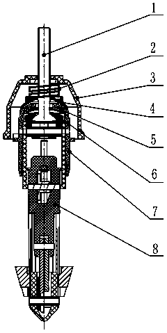
[0015] This embodiment is applicable to the situation of low yarn drawing tension. The boom bolt 1 is fixed to the spinning frame hanger frame through the upper nut, the boom bolt 1 is fixed to the hanger cap 3 through the nut in the middle of the screw rod, and a high-Gauss magnet (magnet) with SN polarity is set at the tail of the boom bolt 1 The piece 5 and the bearing piece 6 are fitted with a damping ring 4 that slides against the inner sleeve 7 of the hanging spindle, and a damping spring 2 is set between the outside of the top of the damping ring 4 and the inside of the top of the hanging spindle cap 3, and the main body of the hanging spindle 8 is mounted Roving for spinning. All plastic parts are made of polyoxymethylene.

[0016] For cotton roving: The magnetic repulsion force controls the weight of the roving: 4kg~30...


PUM


Abstract

The invention discloses a magnetic levitation automatic constant yarn leading tension roving serial suspension spindle. The suspension spindle comprises a suspension spindle body and a suspension spindle cap. A suspension rod bolt is fixed in the axial direction of the suspension spindle cap, the head portion of the suspension rod bolt is disposed on the outside of the suspension spindle cap, and the tail portion of the suspension rod bolt is disposed on the inside of the suspension spindle cap. A suspension spindle inner sleeve is arranged in the suspension spindle cap and is fixedly connected with the suspension spindle body through a pin, a group of Gaussian magnets opposite in SN polarity are sleeved on the tail portion of the suspension rod bolt in the axial direction and comprise floating sheets and bearing sheets. A damping ring in sliding contact is arranged above the suspension spindle inner sleeve, a damping spring is sleeved between the outside of the top of the damping ring and the inside of the top of the suspension spindle cap, and the suspension spindle cap is sleeved on the upper portion of the damping spring. The suspension spindle has the advantages of being applicable to all spun yarn leading tension conditions, enabling the yarn leading tension to be constant automatically along with the roving weight constant change during spinning, preventing breaking and falling during yarn leading and being simple in structure, convenient to promote and long in service life.

Description

technical field [0001] The invention relates to the field of textile and textile machinery, especially the roving series hanging spindles with automatic constant yarn drawing tension in the raw material series spinning machine parts of cotton spinning, hemp spinning, silk spinning, wool spinning and chemical fiber spinning. Background technique [0002] In the textile process, it goes through the roving process and then to the spinning process. The roving spun in the roving process is wound on the roving bobbin, and then the roving bobbin is loaded on the hanging spindle installed on the spinning frame, and then the roving is drawn into the spinning frame for further processing. Next processing. With the running of the spinning frame, the roving is continuously drawn into the spinning frame from the roving bobbin. In order to make the traction speed uniform, the technology of 20 years ago has been used on the hanging spindle, that is, ...

Claims


Application Information

Patent Timeline
Patent Type & Authority Applications(China)
IPC IPC(8): D01H1/18D01H13/10
Inventor 王宇锋孔宪生毛新益
Owner 江阴市通隆纺织机械有限公司
Learn More