Constant-tension pay-off device for overhead line system

A technology of pay-off device and tension device, which is applied in the field of constant tension pay-off device for catenary, and can solve the problems that the pay-off tension cannot be kept constant.

Pending Publication Date: 2021-11-02
CRCC HIGH TECH EQUIP CORP LTD +1
View PDF0 Cites 0 Cited by
  • Summary
  • Abstract
  • Description
  • Claims
  • Application Information

AI Technical Summary

Problems solved by technology

[0003] In the embodiment of the present application, a catenary constant tension pay-off device is provided, which is mainly used to solve the related problem that the pay-off tension of the catenary constant tension pay-off device cannot be kept constant

Method used


Image

  • Constant-tension pay-off device for overhead line system
  • Constant-tension pay-off device for overhead line system
  • Constant-tension pay-off device for overhead line system

Examples


Embodiment Construction

[0029] In order to make the technical solutions and advantages in the present application, the exemplary embodiments of the present application will be described in more detail below with reference to the accompanying drawings, and Not the exhaustion of all embodiments. It should be noted that the features of the present application and the features in the embodiments in the present application can be combined with each other in the case of an unable conflict.

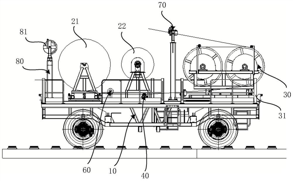
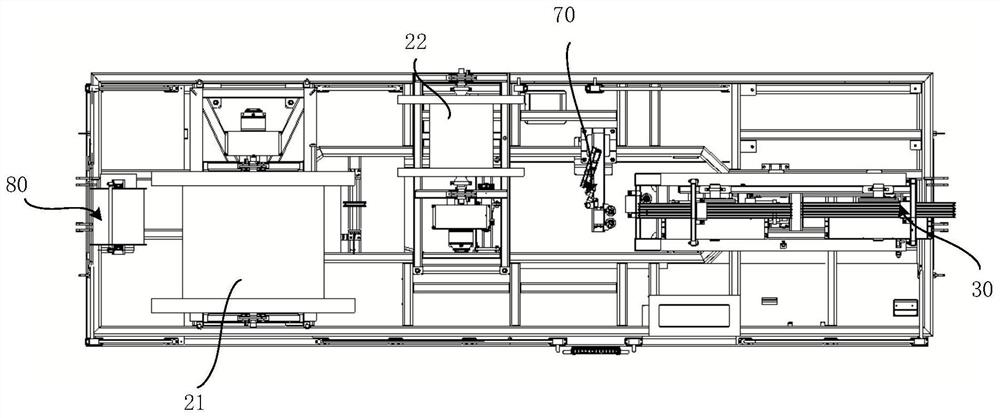
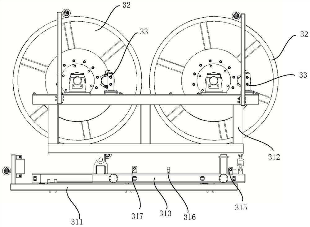
[0030] figure 1 The configuration is shown in the configuration of the contact network constant tension disposed device according to an embodiment of the present application; figure 2 It is shown in figure 1 Top view; image 3 It is shown in the configuration of the tension device provided by an embodiment of this application; Figure 4 It is shown in image 3 Top view; please refer to Figure 1 - Figure 4 . This embodiment provides a contact network constant tension unit, including:

[0031] The rack 10, and the rack 10 is p...


PUM


Abstract

The embodiment of the invention provides a constant-tension pay-off device for an overhead line system. The device comprises a rack, a wire coil, a tension device, a wire inlet force measuring device, a wire outlet force measuring device and a controller, and a driving device is arranged below the rack; the wire coil is arranged on the rack, a to-be-laid cable is wound on the wire coil, and a wire inlet brake is arranged on the wire coil; the tension device is arranged at the end, deviating from the wire coil, of the rack and comprises a tension frame arranged on the rack and two tension wheels arranged on the tension frame, and wire outlet brakes are arranged on the tension wheels. The inlet wire force measuring device is arranged between the wire coil and the tension device and is used for measuring the inlet wire tension of the cable; the outgoing line force measuring device is arranged on the tension device and is used for measuring the outgoing line tension of the cable; and the controller is used for controlling the wire inlet brake to clamp or loosen the wire coil and the wire outlet brake to clamp or loosen the tension wheel according to the wire inlet tension and the wire outlet tension. When the constant-tension pay-off device for the overhead line system is used, the wire outlet tension can be kept constant.

Description

Technical field [0001] The present application relates to the field of railway construction equipment, and more particularly to a contact network constant tension dispatcher. Background technique [0002] The contact network is the main frame of the railway electrical engineering. It is a special form of high-voltage power transmission lines that supply power to the electric locomotive over the iron route, and the power-to-electric bow is currently flowing. The construction of the contact network needs to hold up the bearings, contact lines, and other auxiliary clues. In order to ensure the quality of the disparity, the construction of the above cables and the subsequent maintenance replacement are required to use a constant tension release device. At present, the domestic stereotype of the domestic railway department is poorly controlled with constant tension, and the tension control range is small. Inventive content [0003] In the present application embodiment, a contact net...

Claims


Application Information

Patent Timeline
Patent Type & Authority Applications(China)
IPC IPC(8): H02G7/00H02G1/02B65H59/40B65H59/18B61C17/00
CPCH02G7/00H02G1/02B65H59/18B65H59/40B61C17/00B65H2701/34
Inventor 史天亮马功民徐元成张亮石磊黄新霞付波祁元梁强武宁邬涛文骥笠李剑刘旭张晟文延中李美香
Owner CRCC HIGH TECH EQUIP CORP LTD
Why Eureka
Try Eureka