Lifting handle mounting structure of air conditioner outdoor unit and air conditioner

An air conditioner outdoor unit and installation structure technology, which is applied to air conditioning systems, space heating and ventilation, household heating, etc. The effect of saving packaging space and convenient transportation

Active Publication Date: 2015-07-01
GREE ELECTRIC APPLIANCES INC
View PDF5 Cites 3 Cited by
  • Summary
  • Abstract
  • Description
  • Claims
  • Application Information

AI Technical Summary

Problems solved by technology

[0002] During the after-sales installation process of air conditioner models with a cooling capacity of 3P, two installers are required, and the two installers cooperate with each other to carry the outdoor unit of the air conditioner; most of the outdoor units of the air conditioner of the existing models have large The handle is located on the center plane of the whole machine, which is convenient for carrying personnel on the right side; however, there is only one handle on the left side, which is not on the center plane. Due to the limitation of the installation space of the handle by the condenser, the left handle is generally installed on the The position on the left side and the rear side, so that when the after-sales installers carry the outdoor unit of the air conditioner on the left side, the outdoor unit of the air conditioner is in an unbalanced state, and it is very unsafe to carry; in addition, the handle on the left side generally exceeds the space of the shell , which increases the width of the whole machine, resulting in a larger installation space
At the same time, the left support bar of the existing air-conditioning outdoor unit is fixed by four screws, two on the upper and lower sides. Although the fixing is firm, the number of screws is large, which consumes assembly man-hours; the installer on the left handle side is inconvenient to carry the air conditioner. The outdoor unit has potential safety hazards; the left handle exceeds the outdoor unit casing, occupying more packaging space

Method used


Image

  • Lifting handle mounting structure of air conditioner outdoor unit and air conditioner
  • Lifting handle mounting structure of air conditioner outdoor unit and air conditioner
  • Lifting handle mounting structure of air conditioner outdoor unit and air conditioner

Examples


Embodiment Construction

[0030] In order to make the object, technical solution and advantages of the present invention clearer, the handle installation structure of the air conditioner outdoor unit and the air conditioner of the present invention will be further described in detail with reference to the accompanying drawings and embodiments. It should be understood that the specific embodiments described here are only used to explain the present invention, not to limit the present invention.

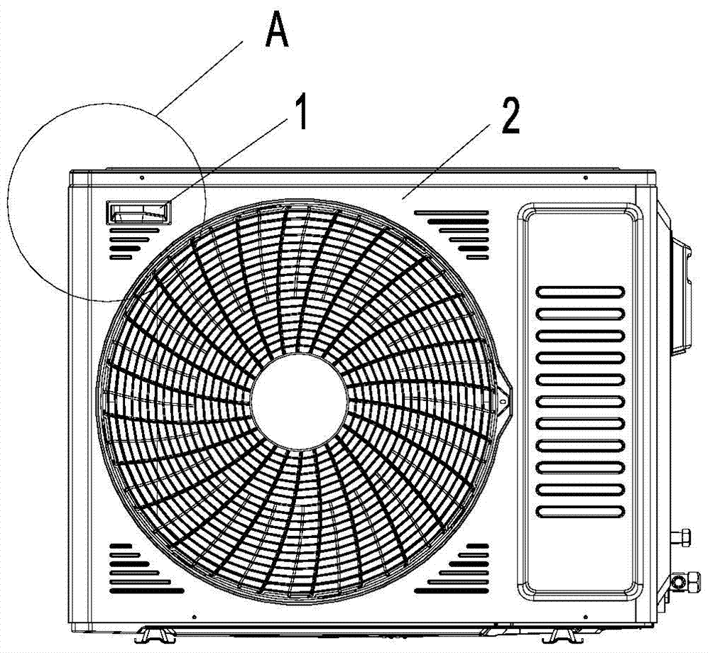
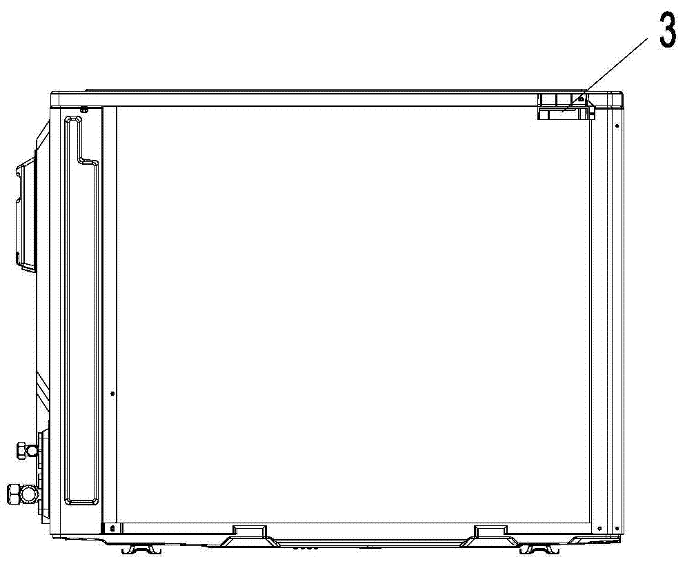
[0031] refer to Figure 1 to Figure 12 , an embodiment of the handle installation structure of the air conditioner outdoor unit of the present invention includes a main handle 1 and an auxiliary handle 3, the main handle 1 and the auxiliary handle 3 are all arranged at the same end (left end) of the outdoor unit, the main handle 1 and the auxiliary handle 3 are arranged oppositely, the main handle 1 is placed on the air outlet side of the outdoor unit, and the auxiliary handle 3 is placed on the air inlet side ...


PUM


Abstract

The invention provides a lifting handle mounting structure of an air conditioner outdoor unit. The lifting handle mounting structure comprises a main lifting handle and an auxiliary lifting handle, wherein the main lifting handle and the auxiliary lifting handle are both arranged on one side of the outdoor unit; the main lifting handle and the auxiliary lifting handle are oppositely arranged; the main lifting handle is arranged on the air outlet side of the outdoor unit; the auxiliary lifting handle is arranged on the air inlet side of the outdoor unit; the main lifting handle is fixed to a housing of the outdoor unit; the auxiliary lifting handle is fixed to a top cover of the outdoor unit. The invention also relates to an air conditioner. According to the lifting handle mounting structure of the air conditioner and the air conditioner, the main lifting handle and the auxiliary lifting handle are arranged on the same end of the outdoor unit at the same time, the carrying is convenient, the packaging space is saved, screws used for fixing a left supporting bar are omitted, and the assembly efficiency is improved.

Description

technical field [0001] The invention relates to the refrigeration field, in particular to a handle installation structure of an air conditioner outdoor unit and an air conditioner. Background technique [0002] During the after-sales installation process of air conditioner models with a cooling capacity of 3P, two installers are required, and the two installers cooperate with each other to carry the outdoor unit of the air conditioner; most of the outdoor units of the air conditioner of the existing models have large The handle is located on the center plane of the whole machine, which is convenient for carrying personnel on the right side; however, there is only one handle on the left side, which is not on the center plane. Due to the limitation of the installation space of the handle by the condenser, the left handle is generally installed on the The position on the left side and the rear side, so that when the after-sales installers carry the outdoor unit of the air condi...

Claims


Application Information

Patent Timeline
Patent Type & Authority Applications(China)
IPC IPC(8): F24F1/06
CPCF24F1/06
Inventor 陈志伟熊军高旭高智强
Owner GREE ELECTRIC APPLIANCES INC
Why Eureka
Try Eureka