Optical magnifying combination mirror, head-mounted display optical system and equipment
A technology of optical magnification and combined mirrors, which is applied in the field of optics, can solve the problems of incompatibility between field of view and product volume and weight, and achieve the effects of enhancing immersion, expanding peripheral vision, and reducing discomfort
- Summary
- Abstract
- Description
- Claims
- Application Information
AI Technical Summary
Problems solved by technology
Method used
Image
Examples
Embodiment 1
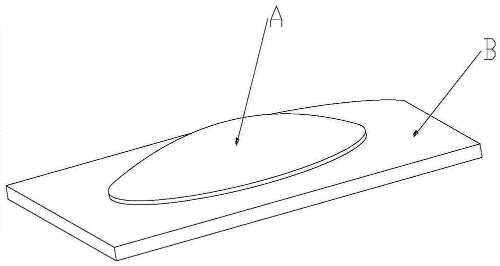
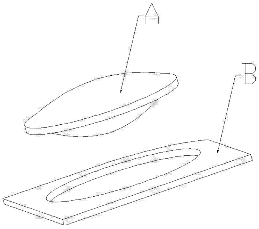
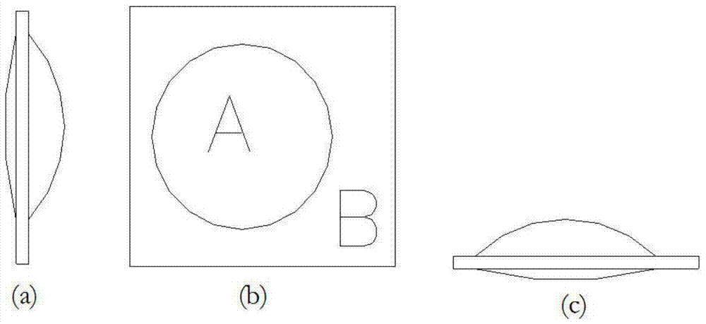
[0053] see Figure 7 , is a schematic structural diagram of the binocular head-mounted display optical system, including the image display source 1 shared by the left and right eyes (the image display source 1 can be a large screen divided into left and right screens, or two separate left and right small screens) and left and right two screens. A group of optical magnifying glass groups, each group of optical magnifying glass groups is composed of a piece of optical magnifying combination mirror 2, the light information displayed by the image display source 1, and the projected virtual image enlarged by the optical magnifying combination mirror 2 is received by human eyes. In the present embodiment, the central lens part (central region A) of the optical magnification combined mirror 2 is cemented by two circular aspheric lenses with the same diameter, that is to say, the central region A of the main mirror 21 is a combined convex lens; Area B is a plane-based Fresnel lens hol...
Embodiment 2
[0058] see Figure 9 , the head-mounted display optical system in this embodiment has an image display source 1 and two sets of optical magnifying glass groups on the left and right, and each group of optical magnifying glass groups is composed of an optical magnifying combination lens 2 and two focusing sheet-type optical elements 3, and the two focusing sheets The optical element 3 is located between the optical magnifying lens 2 and the image display source 1, and the two focusing sheet optical elements 3 in each group of optical magnifying lenses can be a flat base Fresnel lens and a curved base Fresnel lens. lens. The light information displayed by the image display source 1 first passes through the focusing thin optical element 3, and then enters the human eye through the optical magnifying combination mirror 2
Embodiment 3
[0060] see Figure 10 The head-mounted display optical system in this embodiment has an image display source 1 and two groups of optical magnifying glass groups on the left and right, and each group of optical magnifying glass groups consists of an optical magnifying combination mirror 2 and a focusing thin optical element 3 (the present embodiment selects a flat base phenanthrene Neel lens), the light information displayed by the image display source 1 first passes through the focusing thin optical element 3, and then enters the human eye through the optical magnifying combination mirror 2. In this embodiment, the central area A of the optical magnification combined mirror 2 is a circular aspheric lens, and the edge area B is a Fresnel lens hollowed out in the center. The structure of the lens part is marked as Figure 11 As shown, their respective parameters can be referred to Table 2. In this embodiment, when the optical magnifying combination mirror 2 satisfies the param...
PUM
 Abstract
Description
Claims
Application Information
 - R&D
- Intellectual Property
- Life Sciences
- Materials
- Tech Scout
- Unparalleled Data Quality
- Higher Quality Content
- 60% Fewer Hallucinations
Browse by: Latest US Patents, China's latest patents, Technical Efficacy Thesaurus, Application Domain, Technology Topic, Popular Technical Reports.
© 2025 PatSnap. All rights reserved.Legal|Privacy policy|Modern Slavery Act Transparency Statement|Sitemap|About US| Contact US: help@patsnap.com


