
A pressure automatic compensation type pressure difference injection particle continuous injection device

A technology of automatic compensation and pressure compensation, applied in drilling equipment, drilling equipment and methods, earthwork drilling, etc., can solve the problems of wear, restricting the commercialization process of particle impact drilling technology, poor sealing performance of screw extruders, etc. Improve work efficiency, good anti-blocking effect, safe and reliable use

Inactive Publication Date: 2017-02-22
CHINA UNIV OF PETROLEUM (EAST CHINA)
View PDF5 Cites 0 Cited by
  • Summary
  • Abstract
  • Description
  • Claims
  • Application Information

AI Technical Summary

Problems solved by technology

[0005] In the process of particle impact drilling, it is required that the particles must be uniformly injected into the high-pressure main manifold with a fixed volume ratio, and the concentration of the particles can be continuously adjusted. The commonly used screw extrusion injection method is poor in sealing performance of the screw extruder. And the wear is serious, which limits its popularization and application
The above situation seriously restricts the commercialization process of particle impact drilling technology, and the problems existing in the particle injection device need to be solved urgently

Method used


Image

  • A pressure automatic compensation type pressure difference injection particle continuous injection device
  • A pressure automatic compensation type pressure difference injection particle continuous injection device
  • A pressure automatic compensation type pressure difference injection particle continuous injection device

Examples


Embodiment Construction

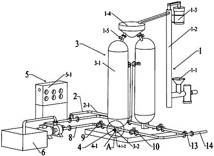
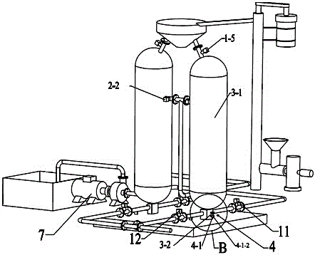
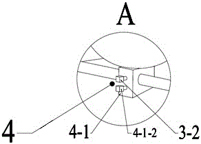
[0038] combined with Figure 1-13 , to further describe the present invention:

[0039] A pressure automatic compensating type differential pressure injection particle continuous injection device, including a particle lifting filling system (1), a pressure compensation system (2), a double-tank injection system (3), an anti-blocking mixing system (4) and a circuit The control system (5), the particle lift filling system (1) is connected to the inlet of the double-tank injection system (3), and the side wall of the double-tank injection system (3) is connected to the pressure compensation system (2). The bottom of the system (3) is connected to the anti-blocking mixing system (4), and the circuit control system (5) is installed on one side; the particle lifting filling system (1) lifts the particles to the double tank injection system (3) middle; the pressure compensation system can pre-boost the particle injection tank (3-1) of the double-tank injection system (3) to the work...


PUM


Abstract

The present invention relates to a device and method for continuously injecting particles by differential pressure ejection with automatic pressure compensation, and its technical solution includes a particle lifting filling system, a pressure compensation system, a double-tank injection system, an anti-blocking mixing system and a circuit control system, It belongs to the technical field of petroleum drilling engineering and is suitable for the continuous injection of particles in particle impact drilling. The pressure compensation system can raise the pressure in the particle injection tank to the working pressure in advance; the double tank injection system is composed of interchangeable The double tanks are connected in parallel to ensure the continuous injection of particles; the anti-blocking mixing system can make the particles controllable and adjustable be injected into the mixing chamber while avoiding particle blockage, and fully mix with the drilling fluid. The invention can realize the continuous injection of particles during particle impact drilling, can work continuously for a long time, ensures the controllable and adjustable particle concentration, avoids the occurrence of particle clogging accidents, and the particles and drilling fluid are evenly mixed; the structure is reasonable and compact, and the use is safe Reliable and can greatly shorten the drilling cycle.

Description

technical field [0001] The invention relates to a petroleum drilling engineering technology, in particular to a pressure automatic compensating type differential pressure ejection particle continuous injection device. Background technique [0002] Particle impact drilling technology is one of the effective ways to increase the drilling speed of deep wells / ultra-deep wells and hard formations, and the particle injection device is the premise and key to the realization of particle impact drilling technology. Fundamentally speaking, the core of particle injection device research is how to integrate Steel particles are continuously injected into the high-pressure drilling fluid at a certain rate. [0003] At present, the existing particle injection devices at home and abroad cannot really realize the continuous injection of particles. Even if the double injection pipe injection device is used, there are obvious disadvantages in application. When the two pipes alternate, the low...

Claims


Application Information

Patent Timeline
Patent Type & Authority Patents(China)
IPC IPC(8): E21B7/16
CPCE21B7/16
Inventor 王瑞和王方祥周卫东申瑞臣李罗鹏田茂法蓝海峰
Owner CHINA UNIV OF PETROLEUM (EAST CHINA)
Learn More