Low-resistance and high-efficiency locking method and device for quick-opening door of pressure vessel

A pressure vessel, low-resistance and high-efficiency technology, applied in pressure vessels, fixed-capacity gas storage tanks, gas/liquid distribution and storage, etc., can solve problems such as unfavorable automatic control, unfavorable safe production, and locking hooks that cannot be locked. , to achieve low-resistance and high-efficiency fast-opening door locking method, facilitate automatic control, and reduce the effect of power input

Active Publication Date: 2017-03-08
ZHEJIANG DONGOU FILTERING MASCH MFG CO LTD
View PDF7 Cites 0 Cited by
  • Summary
  • Abstract
  • Description
  • Claims
  • Application Information

AI Technical Summary

Problems solved by technology

In the above-mentioned several structural principles, the cylinder or oil cylinder is used as the power source, and the displacement of the slope is used to generate the compression to achieve the purpose of locking. However, a large force is required to act on the slope. If the processing accuracy is not enough, the equipment is not properly maintained. , will cause the following three adverse consequences: (1) the locking hook cannot be locked, and it is necessary to manually hammer the head end of the locking hook to make it locked, which is not conducive to the realization of automatic control; (2) the locking hook is not locked In place, it is easy to cause decoupling or even explosion, which will cause safety accidents and is not conducive to safe production; (3) the inclined iron and inclined pad iron of the locking device are easy to rust during use, making it very difficult to open the locking hook

Method used


Image

  • Low-resistance and high-efficiency locking method and device for quick-opening door of pressure vessel
  • Low-resistance and high-efficiency locking method and device for quick-opening door of pressure vessel
  • Low-resistance and high-efficiency locking method and device for quick-opening door of pressure vessel

Examples


Embodiment Construction

[0027] The present invention will be further described below in conjunction with the accompanying drawings and embodiments, but not as a basis for limiting the present invention.

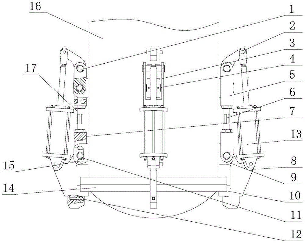
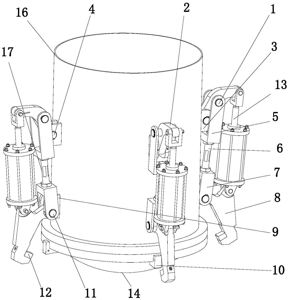
[0028] Example. The fast-opening low-resistance and high-efficiency locking method of the pressure vessel is characterized in that: a power source is used to expand the locking mechanism of the slider crank, and the locking hook connected to the locking mechanism of the slider crank is wound around the third pin shaft fixed on the pressure vessel. Rotate until it fits the inclined pad iron, and the inclined iron on the locking hook does not touch the inclined pad iron; as the power source continues to expand, the arm of the crank slider locking mechanism will drive the adjustable pull rod combination As the parts move, the locking hook is also lifted upwards until the bottom cover is locked; the centerlines of the first pin, the second pin and the third pin on the crank slider locking mechanism are ...


PUM


Abstract

The invention discloses a low-resistance high-efficiency locking method for a quick opening valve of a pressure container. The low-resistance high-efficiency locking method is characterized in that a crank slider locking mechanism is unfolded by a power source, the locking hook of the crank slider locking mechanism is connected to rotate around a third hinge pin fixed on the pressure container until the locking hook fits to a slope sizing block, and tapered iron on the locking hook does not touch with the slope sizing block; when the power source is continuously unfolded, the support arm of the crank slider locking mechanism drives an adjustable pull rod assembly to move, the locking hook lifts upward until a bottom cover is locked; the axes of first, second and third hinge pins on the crank slider locking mechanism are positioned in the same plane, the locking hook is lifted to the highest point, and the resistance force arm of the pull rod is absent; when the power source is again unfolded, the inner side of the support arm acts on the outer wall of the pressure container so that the bottom cover is in a self-locking state. According to the locking method, the bottom cover is locked and the hook is opened by a low-resistance high-efficiency method, and the self-locking state can be realized, thereby omitting the power source, reducing energy consumption and use cost, and improving production security.

Description

technical field [0001] The invention relates to the field of a quick-opening device for a pressure vessel, in particular to a low-resistance and high-efficiency locking method and device for a quick-opening door of a pressure vessel. Background technique [0002] Quick-opening pressure vessels can realize the opening and closing of the container door in a short time, greatly improving production efficiency, and have been widely used in chemical, building materials, food, textile, aerospace, medical, paper and other industrial fields. There are many structural forms of quick-opening devices, but according to their basic principles, they can be roughly divided into five categories: clamp type, gear type, compression type, split ring type and mobile type. [0003] In the actual production process, considering the need to take out the finished product or residue from the quick-opening pressure vessel more conveniently, a traditional compression-type bottom quick-opening device i...

Claims


Application Information

Patent Timeline
Patent Type & Authority Patents(China)
IPC IPC(8): F16J13/00
CPCF16J13/00
Inventor 宋志骥余金水胡良分聂孟春
Owner ZHEJIANG DONGOU FILTERING MASCH MFG CO LTD
Why Eureka
Try Eureka