Adjustable open-circuit guide circuit

An adjustable and guide plate technology, applied in the direction of circuits, printed circuit components, electrical components, etc., can solve problems such as the difficulty of debugging and adjusting impedance values

Inactive Publication Date: 2005-10-05
MITAC INT CORP
View PDF0 Cites 0 Cited by
  • Summary
  • Abstract
  • Description
  • Claims
  • Application Information

AI Technical Summary

Problems solved by technology

However, since the open guide plate is directly formed on the printed circuit, once the plate making is completed, the length of the open guide plate on it is fixed and is not easy to change.
In this way, the related debugging (debugging) work (adjusting the impedance value) will become quite difficult

Method used


Image

  • Adjustable open-circuit guide circuit
  • Adjustable open-circuit guide circuit
  • Adjustable open-circuit guide circuit

Examples


Embodiment Construction

[0013] The same components are denoted by the same reference numerals below.

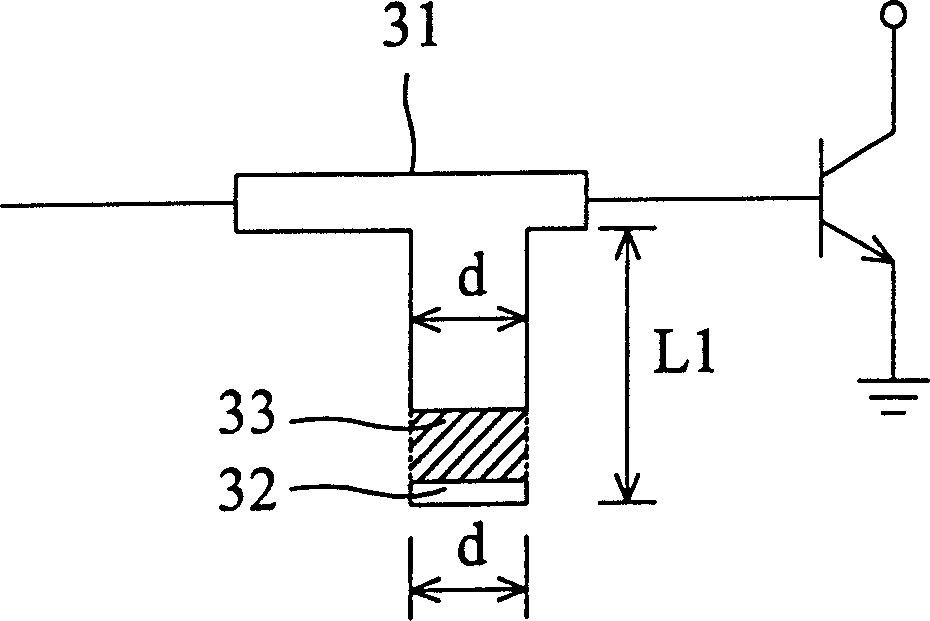
[0014] Figure 3a is a schematic diagram of an adjustable open flipper circuit configured monolithically in accordance with the present invention. exist Figure 3a Among them, a conductive metal sheet 32 ​​whose length is equal to the width d of the open end of the open stud 31 is attached to the open end along with the open stud 31 during circuit layout. an appropriate distance below. When debugging, if it is found that the equivalent capacitance (or inductance) value required by the circuit must be increased, then if Figure 3a As shown, solder 33 is used to connect the metal piece 32 to the open end, so that the total length of the open end of the open guide plate changes from L to L1. Wherein, the solder can be any electrically conductive material such as tin, gold, copper, and the like. Additionally, if Figure 3b As shown, the preset conductive metal sheets can be a plurality of conducti...


PUM


Abstract

An adjustable open stud circuit is soldered with at least one piece of preset conductive metal sheet in the same width with tail end of the open stud in order to achieve the aim of regulating tail end total length of the open stud. It comprises at least one piece of conductive metal sheet in the same width with tail end of the open stud and a conductive connecting assembly, of which at least one piece of conductive metal sheet can be cut into a number of pieces to be placed in intervals provided total width of them should be the same with tail end of the open stud, and in addition, a number of conductive metal sheets disposed in intervals also can be formed in a matrix mode.

Description

technical field [0001] The present invention relates to an open stud circuit (open stud circuit), especially an adjustable open stud circuit (tunable open stud circuit). A conductive metal pad is placed to extend the length of the open guide plate to the end of the metal plate, thereby achieving the purpose of adjusting the total length of the open end of the open guide plate. Background technique [0002] In areas dealing with radio frequency (RF) and microwave (microwave) applications, figure 1 The Smith chart in is often used to determine impedance-related issues, for example, to determine different impedance matching requirements between interconnected blocks and to determine unknown impedance values. like figure 1 As shown, it uses a small area mapping method (conformal mapping) to map all possible orthogonal passive impedances on a polar diagram with complex reflection coefficients of a radius of unity. Among them, the central axis represents the equivalent resistan...

Claims


Application Information

Patent Timeline
Patent Type & Authority Patents(China)
IPC IPC(8): H01P5/02H01P11/00H05K1/02H05K1/16
Inventor 郑添乾
Owner MITAC INT CORP
Why Eureka
Try Eureka