Adjustable open cirecuit guide plate circuit
An adjustable, guide plate technology, applied in directions including printed electrical components, etc., can solve problems such as difficulty in debugging and adjusting impedance values
- Summary
- Abstract
- Description
- Claims
- Application Information
AI Technical Summary
Problems solved by technology
Method used
Image
Examples
Embodiment Construction
[0020] The following identical components are represented by the same symbols.
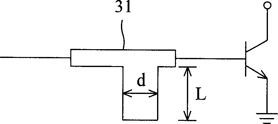
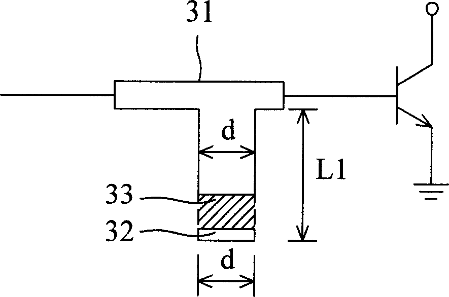
[0021] Figure 3a is a schematic diagram of an adjustable open flipper circuit configured monolithically according to the present invention. exist Figure 3a Among them, a conductive metal sheet 32 whose length is equal to the width d of the open end of the open stud 31 is adhered to the open stud 31 at the end of the open stud along with the open stud 31 during circuit layout. An appropriate distance below. The conductive metal sheet 32 is any metal capable of conducting electricity. When debugging, if it is found that the equivalent capacitance (or inductance) value required by the circuit must be increased, then if Figure 3a As shown, solder 33 is used to connect the conductive metal sheet 32 to the open end, so that the total length of the open end of the open guide plate changes from L to L1. Wherein, the solder can be any electrically conductive material such as tin, gold, copper...
PUM
 Abstract
Description
Claims
Application Information
 - R&D
- Intellectual Property
- Life Sciences
- Materials
- Tech Scout
- Unparalleled Data Quality
- Higher Quality Content
- 60% Fewer Hallucinations
Browse by: Latest US Patents, China's latest patents, Technical Efficacy Thesaurus, Application Domain, Technology Topic, Popular Technical Reports.
© 2025 PatSnap. All rights reserved.Legal|Privacy policy|Modern Slavery Act Transparency Statement|Sitemap|About US| Contact US: help@patsnap.com


