remote diagnosis system

A technology of remote diagnosis and diagnosis system, which is applied in the field of remote diagnosis and can solve problems such as work stoppage

Active Publication Date: 2019-12-31
MANITOWOC CRANE CO LLC
View PDF18 Cites 0 Cited by
  • Summary
  • Abstract
  • Description
  • Claims
  • Application Information

AI Technical Summary

Problems solved by technology

Physical inspection of these sections required dismantling of components, which necessitated a stoppage of work
Disassembly may cause additional wear on components that can be avoided by employing maintenance procedures based on actual unit use

Method used


Image

  • remote diagnosis system
  • remote diagnosis system
  • remote diagnosis system

Examples


Embodiment Construction

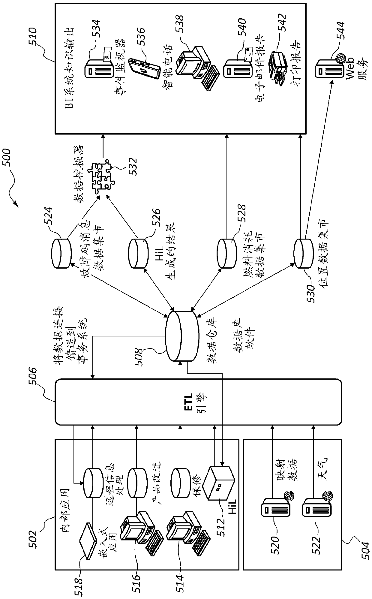
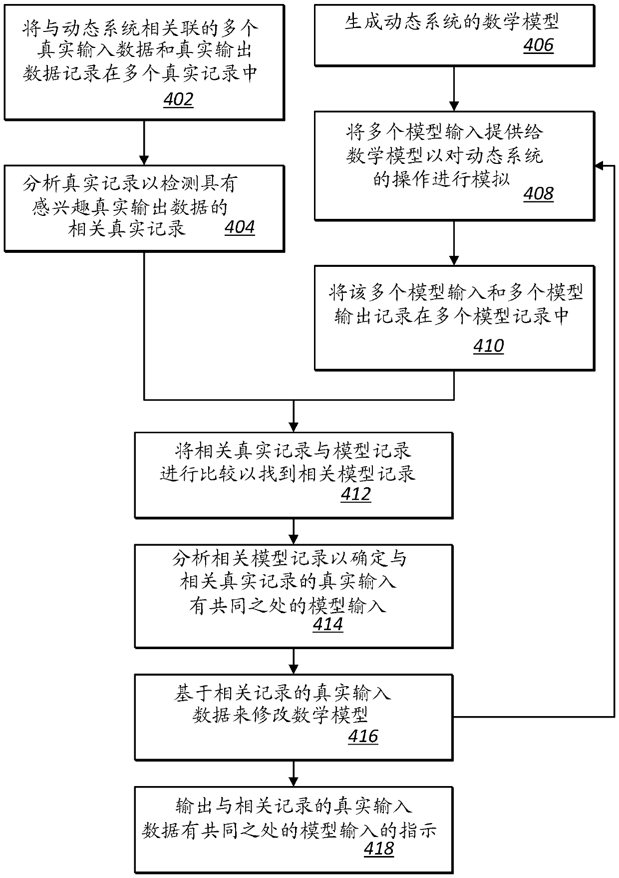
[0016] Embodiments of the invention include systems and methods for accurately predicting maintenance events for dynamic systems. One particular field in which this is useful is the field of construction installations, and more particularly, the field of cranes. Embodiments of the present invention are suitable for other types of dynamic systems, such as industrial plants and commercial food service systems. Embodiments of the invention will now be further described in relation to cranes, although it should be understood that the invention is applicable to other dynamic systems. In the following paragraphs, different aspects of the invention are defined in more detail. Each aspect so defined may be combined with any other aspect or aspects unless clearly indicated to the contrary. In particular, any feature indicated as preferred or advantageous may be combined with any other feature or features indicated as preferred or advantageous.

[0017] figure 1 is a schematic diagr...


PUM


Abstract

The invention relates to a remote diagnosis system for remote diagnosis and development of a dynamic system comprising a dynamic system controlled by a first control system and a plant model controlled by a second control system. The plant model simulates a dynamic system and the inputs and corresponding outputs are recorded to test the control system as well as the operation of the dynamic system. During operation, dynamic system inputs and outputs are recorded. The dynamic system inputs and outputs can then be compared to the plant model inputs and outputs to verify the accuracy of the plant model. The device model can then be updated based on the results of the comparison.

Description

[0001] This patent document claims Provisional U.S. Patent Application Serial No. 61 / 924,923 filed January 8, 2014 on 35 U.S.C. 119(e), the Provisional US Patent Application is hereby incorporated by reference. technical field [0002] The present application relates to the field of field service and diagnostics, and more particularly to systems and methods for remote diagnostics utilizing field data system modeling. Background technique [0003] A dynamic mechanical system can have many components controlled by software. As mechanical systems age, these components experience wear and the software must be able to account for any wear experienced by the components. Dynamic mechanical systems may be subject to maintenance events in the field in the form of software failures in which the software does not properly account for specific situations, or in the form of mechanical events in which mechanical components operate abnormally. [0004] During the design of control softw...

Claims


Application Information

Patent Timeline
Patent Type & Authority Patents(China)
IPC IPC(8): G05B23/02G01M13/00
CPCB66C13/04B66C13/22G06F11/34G06F11/321G05B23/0243G05B17/02
Inventor M.T.奥斯瓦尔德J.S.布莱尔J.A.阿尔格
Owner MANITOWOC CRANE CO LLC
Why Eureka
Try Eureka