
Implantable monitoring probe

a monitoring device and implantable technology, applied in the field of minimally invasive physiological monitoring systems, can solve the problems of inability to complete the les, and inability to rest, etc., to prolong the useful life of the monitoring device, prevent erroneous or stray signals, and save battery power

Inactive Publication Date: 2012-12-04
GIVEN IMAGING LTD
View PDF75 Cites 8 Cited by
  • Summary
  • Abstract
  • Description
  • Claims
  • Application Information

AI Technical Summary

Benefits of technology

The present invention provides a monitoring device for monitoring physiological parameters in a body. The device has a housing with a tissue attachment surface and a pin that can be extended through tissue to secure the device at a specific attachment site. The device can also have a vacuum lumen and a window to allow for visualization of the attachment site. The monitoring device can also have a microprocessor and non-volatile memory to store data and a battery to power the device. The monitoring device can be powered off and on to conserve battery power. The invention also provides a method for attaching the monitoring device to a tissue surface and a method for monitoring physiological parameters.

Problems solved by technology

Frequent reflux episodes may result in a potentially severe problem known as gastroesophageal reflux disease (GERD).
Another cause of GERD is decreased resting tone of the LES, which produces incompetence (incomplete closing) of the LES.
Such pH changes, however, can be difficult to prove to be caused by true gastroesophageal reflux, and in some instances may not be caused by reflux.
The use of radioactive material and the expense of stationary or ambulatory gamma cameras make the radioisotope method for detection of reflux unattractive.
Almost invariably, the catheter's presence is very uncomfortable to patients, who frequently develop a sore throat and rhinorrhea (runny nose) because of local irritation of oropharyngeal and nasopharyngeal mucous membranes, respectively, from the catheter.
In addition, many patients are embarrassed to be seen in public with the catheter assembly attached to their faces.
This increased swallowing introduces a significant amount of air into the stomach, which can cause abdominal discomfort.
Finally, increased swallowing in response to the catheter's presence may erroneously raise a patient's intraesophageal pH readings because saliva is alkaline.

Method used


Image

  • Implantable monitoring probe
  • Implantable monitoring probe
  • Implantable monitoring probe

Examples


Embodiment Construction

[0055]The present invention provides a method and system for monitoring physiological parameters within a body lumen (cavity). The invention also comprises methods for attaching a physiological parameter monitor to a wall of a body lumen. The term “lumen” as used herein refers to the space within a tubular wall (e.g., a vessel) or the cavity within a hollow organ. While the invention is described in detail as applied to the human esophagus, those skilled in the art will appreciate that it can apply to other body lumens or cavities, such as those of the stomach, colon, rectum, bladder, uterus, vagina, biliary ducts (including the common bile duct), or blood vessels. The term “esophagus” in this discussion includes the lower esophageal sphincter (LES). Where different embodiments have like elements, like reference numbers are used.

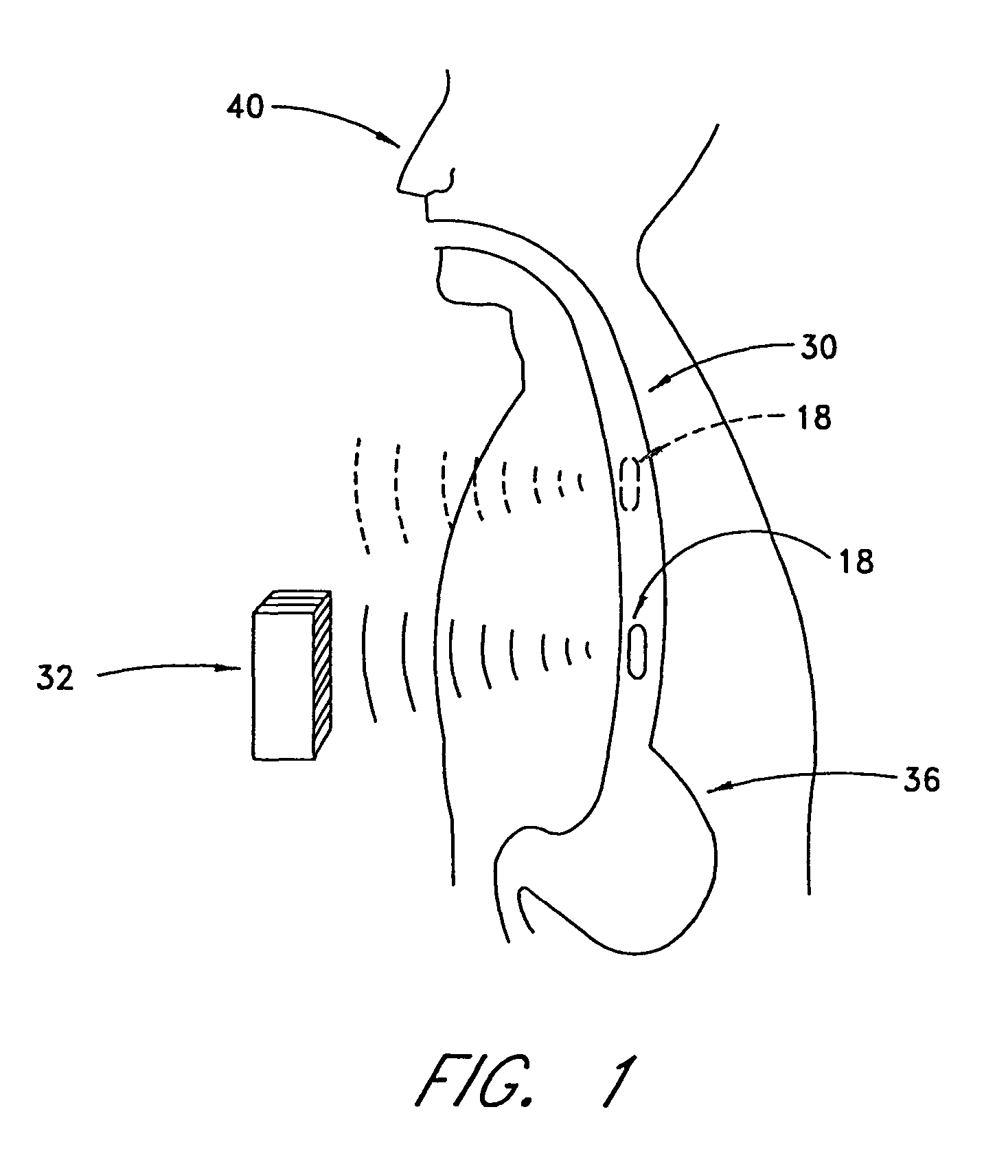
[0056]FIG. 1 illustrates how physiological parameter data can be relayed by the monitor 18, which is positioned within the esophagus 30, to a radiofrequency...


PUM

PropertyMeasurementUnit
pressureaaaaaaaaaa
pressureaaaaaaaaaa
timeaaaaaaaaaa

Abstract

Disclosed is an ambulatory system for monitoring one or more physiological parameters in a body lumen, such as the esophagus. The system includes an implantable probe having a sensor for the physiological parameter and a transmitter for transmitting data to an external receiver. The probe may be used for monitoring any of various physiological parameters, including pH, temperature, and pressure, within the esophagus or other body lumens. Methods and deployment catheters are also disclosed.

Description

BACKGROUND OF THE INVENTION[0001]This application is a continuation of U.S. application Ser No. 10 / 687,336, filed Oct. 16, 2003, which is a divisional of U.S. application Ser No. 09 / 544,373, filed Apr. 6, 2000, now issued as U.S. Pat. No. 6,689,056, which is a continuation-in-part of U.S. application Ser No. 09 / 287,617, filled Apr. 7, 1999, now issued as U.S. Pat. No. 6,285,897. The entire count of each of these U.S. Applications is incorporated herein by reference.FIELD OF THE INVENTION[0002]The present invention relates to minimally invasive physiological monitoring systems. More particularly, the present invention relates to an implantable probe for monitoring one or more parameters in the esophagus, such as pH, in connection with the detection of gastroesophageal reflux disease.DESCRIPTION OF THE RELATED ART[0003]Gastroesophageal reflux is a condition in which gastric acid refluxes, or flows in the direction opposite to the normal flow, from the stomach into the esophagus. Frequ...

Claims


Application Information

Patent Timeline
Patent Type & Authority Patents(United States)
IPC IPC(8): A61B5/00A61B5/05G01N27/416A61B5/03A61B5/07
CPCA61B5/0031A61B5/14539A61B5/14546A61B5/4233A61B5/6882A61B1/00147A61B1/041A61B5/0008A61B5/037A61B5/14532A61B1/00148A61B5/073A61B5/42
Inventor KILCOYNE, JOHN T.TSUKASHIMA, ROSSJOHNSON, GEORGE M.KLECHER, CHRISTOPHER
Owner GIVEN IMAGING LTD
Learn More