
Knob coding switch

A technology of coded switches and knobs, which is applied in the direction of electric switches, electrical components, circuits, etc., can solve the problems of no identification, no rotation position display of knob switches, and inability to effectively exert product functions, etc.

Inactive Publication Date: 2017-03-29
褚锦雄
View PDF5 Cites 0 Cited by
  • Summary
  • Abstract
  • Description
  • Claims
  • Application Information

AI Technical Summary

Problems solved by technology

However, traditional mechanical rotary switches can only provide limited level adjustments. In other words, in terms of a single 360-degree rotation, the level adjustment is limited to one rotation, and further rotations cannot produce more level changes. It will not be able to effectively exert the efficacy of the product, and users will not be able to control the product according to their needs
[0004] In addition, the traditional rotary switch does not have the function of displaying the rotation position, or only provides a marking mark on the surface of the switch as the identification of the rotation position
In this way, the positioning during rotation is not easy to be clearly known by the outside world, especially in dark places

Method used


Image

  • Knob coding switch
  • Knob coding switch
  • Knob coding switch

Examples


Embodiment Construction

[0073] The present invention will be further described below in conjunction with the accompanying drawings and specific embodiments, so that those skilled in the art can better understand the present invention and implement it, but the examples given are not intended to limit the present invention.

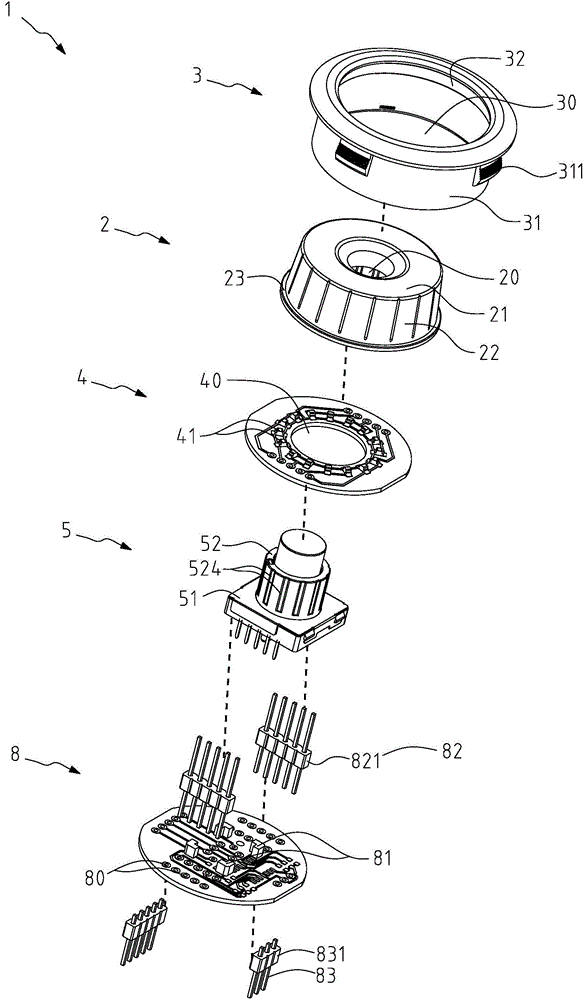
[0074] The knob coding switch 1 of the present invention can be applied to electronic products, electrical products or lighting equipment to control the opening or closing of the application end products, and / or adjust various functions of the products, such as adjusting the intensity of light and shade, volume, wind speed The strength (such as an electric fan) or the size of the fire (such as a gas stove) can provide multi-stage fine function changes.

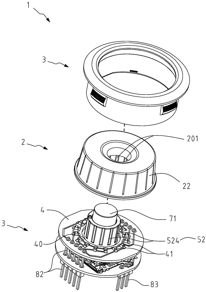
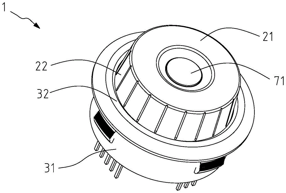
[0075] see Figure 1 to Figure 5 As a preferred embodiment of the present invention, the rotary encoder switch 1 of the present invention includes a cap 2 , a frame 3 , a first substrate 4 , a driving module 5 , and a second subst...


PUM


Abstract

The invention discloses a knob encoding switch which comprises a cap, a sleeve frame, a first substrate, a driving module, and a second substrate. The cap comprises a display surface, a rotating surface, and a shaft sleeve. The driving module comprises a base and a rotating member which is connected to the base in a rotatable manner and is sheathed in the shaft sleeve. The first substrate is arranged on the base and is provided with a plurality of first light-emitting components. The second substrate is arranged below the driving module, and is connected to the first substrate and the circuit board of an application-end product by multiple connecting terminals. The rotating member of the driving module rotates through rotation of the cap, and generates a different encoding signal according to each rotation positioning to control the function of the application-end product. The first light-emitting components can be sequentially started or closed according to the rotation positioning and rotation direction of the cap, and are displayed on the display surface of the cap. The defect that a traditional switch is easy to damage due to positioning by an elastic sheet is effectively solved, and the problem that traditional knob rotation positioning cannot be identified can be solved.

Description

technical field [0001] The present invention relates to a switch, in particular to a rotary coding switch that combines mechanical and rotary coding functions, can provide multi-stage control through continuous rotation, and has a stage display function. Background technique [0002] Electronic products are generally equipped with a switch for turning on or controlling their functions. There are many types of switches, but their purpose is to effectively use the functions of the application end products, such as the speed of the electric fan, the strength of the air conditioner, the volume of the stereo, the brightness of the lamp, and the signal strength of the wireless machine. [0003] It is well known that the traditional mechanical rotary switch is composed of mechanical components. It has a body and a knob pivotally connected to the body for the user to turn. , the metal shrapnel is a cantilever structure, which is very easy to be elastically fatigued due to a period ...

Claims


Application Information

Patent Timeline
Patent Type & Authority Patents(China)
IPC IPC(8): H01H19/02H01H9/16
CPCH01H19/025
Inventor 褚锦雄
Owner 褚锦雄
Learn More