Method for disassembling and assembling grounding wire through self-lockable grounding wire clamp

A technology of grounding wire clips and grounding wires, which is applied in the direction of clip connection, conductor connection, connection, conductive connection, etc., which can solve problems such as jamming, achieve easy removal, and improve labor efficiency.

Active Publication Date: 2015-07-08
STATE GRID CORP OF CHINA +1
View PDF3 Cites 9 Cited by
  • Summary
  • Abstract
  • Description
  • Claims
  • Application Information

AI Technical Summary

Problems solved by technology

[0003] The present invention aims to solve the problem that the existing grounding wire clamp is prone to jamming during the process of installing or removing the grounding wire, and proposes a self-locking grounding wire clamp

Method used


Image

  • Method for disassembling and assembling grounding wire through self-lockable grounding wire clamp
  • Method for disassembling and assembling grounding wire through self-lockable grounding wire clamp
  • Method for disassembling and assembling grounding wire through self-lockable grounding wire clamp

Examples


specific Embodiment approach 1

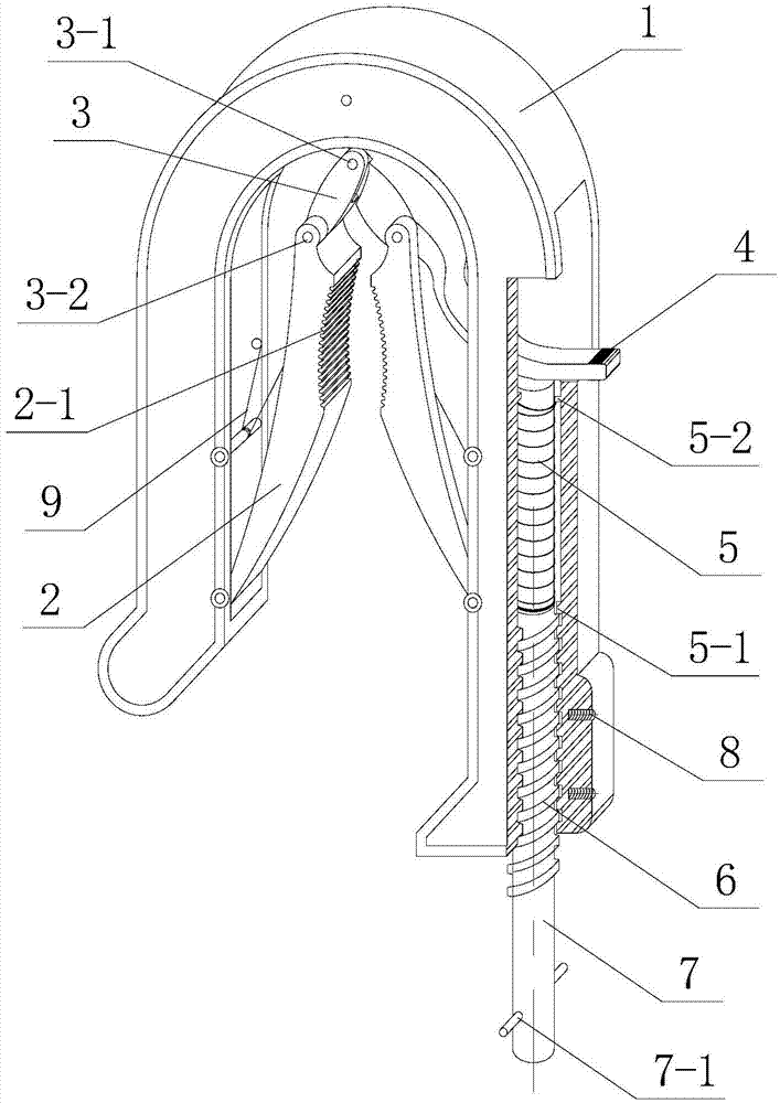
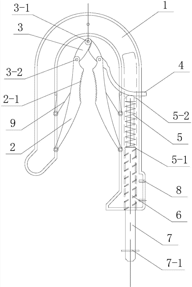
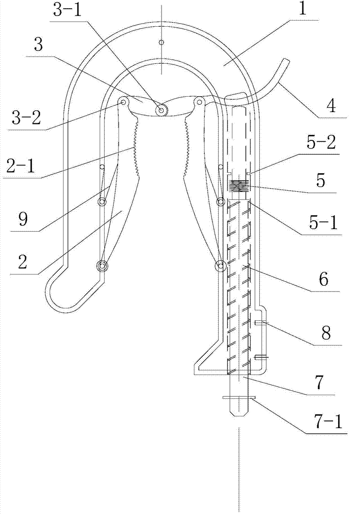
[0019] Specific implementation mode 1. Combination Figure 1 to Figure 3 Describe this embodiment, the method of using the self-locking grounding wire clamp to disassemble and install the grounding wire described in this embodiment, the self-locking grounding wire clamp includes a U-shaped clip body 1, two bow-shaped conductive clips 2, Movable locking piece 3, movable locking piece pressing handle 4, rotating compression spring 5, screw ejector rod 7, connection terminal 8 and clip compression spring 9;

[0020] The main body of the U-shaped clip body 1 is an inverted U-shaped structure, and the inner surface of the U-shaped clip body 1 has a U-shaped groove. The connecting side of the U-shaped clip body 1 and the insulating rod is a hollow structure. Quick thread 6, and the side of U-shaped clip body 1 has a rectangular through hole;

[0021] Two arcuate conductive clips 2 are relatively arranged in the U-shaped area of ​​the U-shaped clip body 1, and the bottom ends of the...

specific Embodiment approach 2

[0029] Specific embodiment two, combine Figure 4 This embodiment is described. This embodiment is a further description of the self-locking ground wire clip described in the first embodiment. Shape groove 4-1 is corresponding with screw mandrel 7.

specific Embodiment approach 3

[0030] Specific embodiment 3. This embodiment and the further description of the self-locking grounding wire clamp described in specific embodiment 1 or 2, the inner sides of the two arcuate conductive clips 2 are provided with arc-shaped depressions, and the two arch-shaped The arc-shaped depressions on the conductive clip 2 are oppositely arranged.

[0031] The inner sides of the two bow-shaped conductive clips 2 described in this embodiment are provided with arc-shaped recesses 2-1 to tighten the ground wire when clamping the ground wire. The line slipped when the line appeared.


PUM


Abstract

The invention discloses a method for disassembling and assembling a grounding wire through a self-lockable grounding wire clamp, and belongs to the technical field of grounding wire clamps. The problem that in the process of assembling or disassembling the grounding wire through an existing grounding wire clamp, blocking is prone to occurrence is solved. According to the method, the grounding wire is disassembled and assembled through the self-lockable grounding wire clamp, the grounding wire is firstly installed on a wiring terminal of the grounding wire clamp, then a movable locking sheet pressing handle of the wire clamp is lifted, and a movable locking sheet is blocked to form self locking after the movable locking sheet is balanced; when the grounding wire is assembled, the grounding wire clamp is hung on a wire through an insulating rod, arch conducting clamping sheets receive pressure applied by clamping sheet compressed springs to drive the movable locking sheet to carry out upward jacking, and the wire is clamped by the arch conducting clamping sheets; when the grounding wire is disassembled, the top end of the insulating rod is inserted into a spiral ejector rod of the grounding wire clamp to be connected with the spiral ejector rod in a clamped mode, the insulating rod is clockwise rotated, the arch conducting clamping sheets are stretched, and the grounding wire clamp is disassembled from the wire. The method is suitable for disassembling and assembling the grounding wire.

Description

technical field [0001] The invention belongs to the technical field of ground wire clips. Background technique [0002] High-voltage grounding wires are widely used in power systems and are installed on both sides of the workplace to prevent the occurrence of electrostatic induction electric shocks near charged objects or sudden electric shocks from equipment that may cause personal electric shocks to staff. At this stage, the commonly used grounding wire clamps are clamped by the spring clips on both sides to tighten the wires, but during the installation and removal of the grounding wire, it is easy to get stuck, especially when the grounding wire is hung in the middle of the wire, the wire has a large slack, and it is often removed. The ground is very difficult. Contents of the invention [0003] The present invention aims to solve the problem that the existing grounding wire clamp is prone to jamming during the process of installing or removing the grounding wire, and...

Claims


Application Information

Patent Timeline
Patent Type & Authority Applications(China)
IPC IPC(8): H01R11/14H01R43/00
CPCH01R11/14H01R43/027
Inventor 赵旭扈洪伟车长友鲍善东
Owner STATE GRID CORP OF CHINA
Why Eureka
Try Eureka