
ILizarov external fixation support

A technology of external fixation and fixed disc, applied in the field of medical devices, can solve the problems of time-consuming, laborious, waste of medical resources, etc., and achieve the effect of facilitating precise adjustment

Active Publication Date: 2015-07-15
SHANGHAI SIXTH PEOPLES HOSPITAL
View PDF8 Cites 1 Cited by
  • Summary
  • Abstract
  • Description
  • Claims
  • Application Information

AI Technical Summary

Problems solved by technology

[0002] The Ilizarov external fixation bracket device is composed of multiple parts, but its assembly, fixation, and adjustment are time-consuming and laborious, especially in the assembly, fixation, and adjustment of the threaded rod and the external fixation ring, which increases the invalid operation time (The operation time is generally about 3-5 hours), which virtually increases the surgical risk of the patient and wastes precious medical resources. At the same time, there is also the problem of imprecise postoperative adjustment, which limits the operation to a certain extent. Wide application of Ilizarov external fixator

Method used


Image

  • ILizarov external fixation support
  • ILizarov external fixation support
  • ILizarov external fixation support

Examples


Embodiment 1

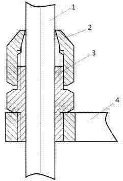
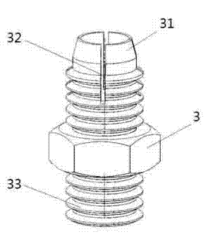
[0018] Such as figure 1 and figure 2 As shown, the embodiment of the present invention provides an Ilizarov external fixation bracket, which includes a fixed disk 4 and a connecting rod, and a plurality of circular holes are evenly distributed on the circumference of the fixed disk 4, and the connecting rod passes through the circular hole and is connected to the On the fixed disk, the connecting rod is 1, and the smooth rod 1 is connected to the disk through the connecting part, and can move up and down through the connecting part. The connection part includes an elastic collet 3 and a lock nut 2, the elastic collet connects the disk 4 and the smooth rod 1, and the elastic collet 3 is externally connected with the lock nut 2. The collet 3 has a conical end portion 31 and a tail portion 33 with an external thread, the conical surface of the end portion is cut to form a plurality of clamping jaws, the lock nut has an internal conical surface matching the conical surface end, ...

Embodiment 2

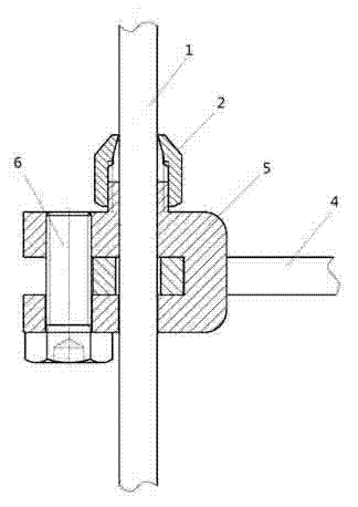
[0021] Such as image 3 and Figure 4 As shown, the embodiment of the present invention provides another Ilizarov external fixation bracket, which includes a fixed disc 4 and a connecting rod, a plurality of circular holes are evenly distributed on the circumference of the fixed disc 4, and the connecting rod passes through the circular hole and is connected to the fixed On the disk 4, the connecting rod is a smooth rod 1, and the smooth rod 1 is connected to the disk through the connecting portion, and can move up and down through the connecting portion. The connection part includes an elastic collet 5 and a lock nut 2 , the elastic collet 5 connects the disc 4 and the smooth rod 1 , and the elastic collet 5 is connected with the lock nut 2 outside. The end portion 51 of the collet 5 has a conical surface and a tail portion 53 of the elastic jaw. The conical surface of the end portion is cut to form a plurality of clamping claws. The elastic jaws have grooves for clamping t...


PUM


Abstract

The invention discloses an ILizarov external fixation support. The ILizarov external fixation support comprises a fixing disc and a connecting bar, wherein a plurality of round holes are uniformly formed in the circumference of the fixing disc; the connecting bar which is a smooth bar penetrates one of the round holes to be connected to the fixing disc through a connecting part; the connecting bar can move up and down through the connecting part. According to the ILizarov external fixation support, the smooth bar replaces a threaded bar, the connecting part is designed at the junction part of the smooth bar and the fixing disc, and the smooth bar is marked with scales to facilitate accurate adjustment; and by adoption of the ILizarov external fixation support, the original operation time is expected to be shortened by more than a half, so that a solid foundation is laid for wide application in clinic practice.

Description

technical field [0001] The invention relates to the technical field of medical instruments, in particular to an Ilizarov external fixation bracket. Background technique [0002] The Ilizarov external fixation bracket device is composed of multiple parts, but its assembly, fixation, and adjustment are time-consuming and laborious, especially in the assembly, fixation, and adjustment of the threaded rod and the external fixation ring, which increases the invalid operation time (The operation time is generally about 3-5 hours), which virtually increases the surgical risk of the patient and wastes precious medical resources. At the same time, there is also the problem of imprecise postoperative adjustment, which limits the operation to a certain extent. Widespread use of Ilizarov external fixators. In view of the above defects, on the basis of keeping the basic principle of the Ilizarov external fixation bracket unchanged, it inherits its advantages and improves some basic comp...

Claims


Application Information

Patent Timeline
IPC IPC(8): A61B17/60
CPCA61B17/60A61B2017/564
Inventor 盛加根盛美贞
Owner SHANGHAI SIXTH PEOPLES HOSPITAL
Learn More