Mechanical transmission roller wing lift force generation device

A generation device and mechanical transmission technology, applied in the direction of passing through cylindrical rotating parts, can solve the problems of low-speed flight performance, large wing area, and poor structural strength of fixed-wing aircraft

Inactive Publication Date: 2015-07-15
董海宁
View PDF5 Cites 4 Cited by
  • Summary
  • Abstract
  • Description
  • Claims
  • Application Information

AI Technical Summary

Problems solved by technology

The relative thickness of the wing and the rotor are relatively thin, and the structural strength is poor
The low-speed flight performance of fixed-wing aircraft is not high, the required wing area is large, and it cannot vertically lift

Method used


Image

  • Mechanical transmission roller wing lift force generation device
  • Mechanical transmission roller wing lift force generation device

Examples


Embodiment Construction

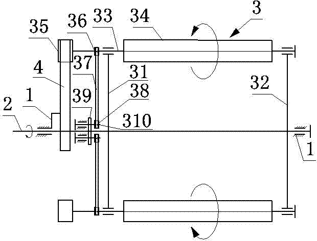
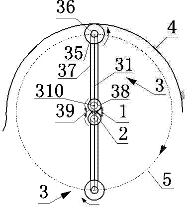
[0010] The present invention will now be described in detail with reference to the drawings: a mechanical drive drum wing lift generating device, comprising a frame 1, a main shaft 2, an arc guide 4 and two rotors 3 with the same structure symmetrically distributed around the main shaft 2; Each rotating wing 3 includes a left rotating arm 31, a right rotating arm 32, a roller shaft 33, a roller wing 34, a guide wheel 35, a driving synchronous wheel 36, a synchronous belt 37, a driven synchronous wheel 38, a gear 39 and a gear shaft 310. The drum wing 34 is a drum that can flexibly rotate around the axis of the drum shaft 33. The main shaft 2 is arranged horizontally, and the left and right ends of the main shaft 2 are respectively mounted on the frame 1 through bearings. The arc-shaped guide rail 4 is longitudinally installed above the horizontal plane of the main shaft 2 and directly above the guide wheel 35. The lower surface of the arc-shaped guide rail 4 is in contact with ...


PUM


Abstract

The invention discloses a mechanical transmission roller wing lift force generation device, and belongs to the technical field of aviation. The mechanical transmission roller wing lift force generation device comprises a rack, a main shaft, an arc guide rail and two rotor wings which are symmetrically distributed on the periphery of the main shaft and are of the same structure. Each rotor wing comprises a left rotating arm, a right rotating arm, a roller shaft, a roller wing, a guide wheel, a driving synchronous wheel, a synchronous belt, a driven synchronous wheel, a gear and a gear shaft. The main shaft is horizontally installed on the rack through a bearing. The lower surface of the arc guide rail makes contact with the guide wheels higher than the horizontal plane of the main shaft. When the guide wheels above the horizontal plane of the main shaft revolve around the axis of the main shaft, the roller shafts connected with the guide wheels will be driven to rotate automatically and the roller wings connected with the roller shafts are driven to rotate automatically. The autorotation direction of the roller wings is opposite to the revolution direction of the roller wings around the main shaft. The guide wheels below the horizontal plane of the main shaft will rotate automatically in the direction opposite to the direction in which the guide wheels above the horizontal plane of the main shaft rotate. The mechanical transmission roller wing lift force generation device is applied to a vertical lift aircraft to be used as a lift force device.

Description

Technical field [0001] A mechanical transmission roller wing lift generating device belongs to the field of aviation technology, and in particular relates to a roller wing thrust generating device. Background technique [0002] Traditional aircraft rely on wings or rotors to generate lift. The wing of an airplane and the rotor of a helicopter are similar in structure. Their cross-sections are all wing-shaped. Lift is generated by air flowing through the upper and lower surfaces of the wing to generate a pressure difference. When determining, the amount of lift they generate is related to the angle of attack, the size of the airfoil and the incoming flow velocity. The adjustment of the lift is achieved by changing the angle of attack, speed or the size of the airfoil. The relative thickness of the wing and the rotor are relatively thin, and the structural strength is poor. Fixed-wing aircraft have poor low-speed flight performance, require a large wing area, and cannot lift verti...

Claims


Application Information

Patent Timeline
Patent Type & Authority Applications(China)
IPC IPC(8): B64C23/02
Inventor 王志成
Owner 董海宁
Why Eureka
Try Eureka