An experimental simulation mechanism for multiphase flow with water entry and aeration

A multiphase flow, experimental simulation technology, applied in fluid dynamics tests, testing of machine/structural components, measuring devices, etc., can solve the problem of lack of experimental methods, lack of sufficient understanding, affecting the trajectory of the model and the formation of multiphase flow. and other issues to reduce interference and ensure effectiveness.

Active Publication Date: 2017-05-24
HARBIN ENG UNIV
View PDF5 Cites 0 Cited by
  • Summary
  • Abstract
  • Description
  • Claims
  • Application Information

AI Technical Summary

Problems solved by technology

However, the research on the development law of multiphase flow entering water is in its infancy, especially the research on the closure behavior of the initial growth of multiphase flow entering water and aeration is lack of sufficient understanding, and there is no experimental method for this problem
The main problem is that the general experimental ventilation system uses pipeline air supply to accurately control the flow rate, but the water entry experiment is in a state of motion, and carrying the ventilation system pipeline will seriously affect the movement trajectory of the model and the formation of multiphase flow. How to simulate water entry in the water cylinder Accurate Determination of Aerated Multiphase Flow and Aeration Volume Reveals Prerequisites for Initial Growth Closure Behavior of Water-Aerated Multiphase Flow

Method used


Image

  • An experimental simulation mechanism for multiphase flow with water entry and aeration

Examples


Embodiment Construction

[0013] The present invention will be further described in detail below in conjunction with the accompanying drawings and specific embodiments.

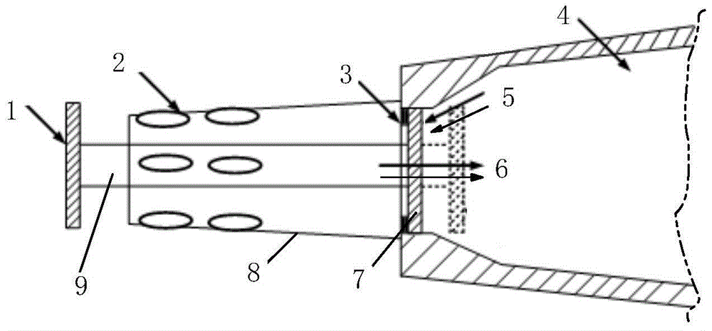
[0014] combine figure 1 , the present invention comprises a conical air collection chamber 4, an annular sealing ring 3 installed at the end of the conical air collecting chamber 4, an airtight seal installed at the end of the conical air collecting chamber 4 and positioned inside the annular sealing ring 3 The cover plate 7, the piston rod 9 fixedly connected to the center of the airtight cover plate 7, and the cavitator 1 connected to the other end of the piston rod 9, and a hollow cylindrical platform 8 is also provided outside the end of the conical air collection chamber 4 , the hollow cylindrical surface 8 is provided with at least six ventilation holes 2 in the circumferential direction, and the intervals between the ventilation holes are equal, and the piston rod 9 is located inside the hollow cylindrical surface 8 .

[0015]...


PUM


Abstract

The invention provides an entry ventilation multiphase flow experiment simulation mechanism. The mechanism comprises a conical air collecting bin, a circular sealing ring mounted at one end of the conical air collecting bin, an airtight cover plate mounted at one end of the conical air collecting bin and located on the inner side of the circular sealing ring, a piston rod fixedly connected with the center of the airtight cover plate and a cavitator connected with the other end of the piston rod, wherein a hollow cylindrical platform is also arranged on the outer side of one end of the conical air collecting bin, at least six vent holes are circumferentially formed in the hollow cylindrical platform at equal intervals, and the piston rod is located in the hollow cylindrical platform. According to the mechanism, the interference caused by an external ventilation pipeline to the experiment and the flow field can be effectively reduced, and the validity of experiment simulation is guaranteed; the sealing state of the airtight cover plate is realized by the aid of the air collecting bin, meanwhile, the air collecting bin is opened under the action of the entry impact load, and effective ventilation during entry is realized.

Description

technical field [0001] The invention relates to an experimental simulation mechanism, in particular to an experimental simulation mechanism for water-entry and aeration multiphase flow. Background technique [0002] With the development and application of multi-phase flow drag reduction technology in water, for the vehicle entering water on the water surface and in the air, in order to achieve ultra-low resistance navigation in water, the ventilation system of the vehicle has started to work before entering the water. So in order to develop the experimental simulation technology of water-entry aeration multiphase flow is the key technology to solve the water-entry aeration multiphase flow. [0003] On the other hand, for ordinary water surface and flying vehicles in the air, they will also cavitate after entering the water. During the subsequent navigation process, the collapse of the cavitation will cause the ballistic instability of the vehicle. May and Waugh pointed out ...

Claims


Application Information

Patent Timeline
Patent Type & Authority Patents(China)
IPC IPC(8): G01M10/00
Inventor 蒋运华张昱李春涛陈拾
Owner HARBIN ENG UNIV
Why Eureka
Try Eureka