
Rotary disc reactor

A reactor and rotary disk technology, applied in the field of reactors, can solve the problems of difficulty in ensuring the heat transfer effect between solid-solid phases and the depth of the pyrolysis reaction, so as to enhance the degree of mixing and the effect of interphase heat transfer, and enhance the mixing efficiency. Effect

Active Publication Date: 2017-12-29
CHNA ENERGY INVESTMENT CORP LTD +1
View PDF5 Cites 0 Cited by
  • Summary
  • Abstract
  • Description
  • Claims
  • Application Information

AI Technical Summary

Problems solved by technology

When the solid heat carrier is used for coal pyrolysis, if there is no necessary mixing measures after the solid heat carrier and coal enter the reactor, it is difficult to ensure the heat transfer effect between the solid and solid phases and the depth of the pyrolysis reaction

Method used


Image

  • Rotary disc reactor
  • Rotary disc reactor
  • Rotary disc reactor

Examples


Embodiment 1

[0075]The raw coal processing capacity of the rotary disk reactor is 500,000 tons per year, and the pyrolysis semi-coke is used as the heat carrier. The temperature of raw coal after drying is 150-200°C, the temperature of heat carrier is 750-800°C, the pyrolysis reaction temperature is 550-650°C, the mass ratio of heat carrier and dry coal is 4:1, and the pyrolysis reaction time is about 30min. The outer diameter of the tray of the rotary disk reactor is 27.5m, the diameter of the discharge pipe is 3.0m, and there are 4 levels of material guide plates. The width of each level from the outside to the inside is about 1.8m, 2.1m, 2.8m and 5.4m. The thickness is 0.4m. The groups of mixing mechanisms set on the guide plates at all levels are 2, 1, 1, and 1 respectively, and each group of mixing mechanisms contains 3 layers of four-petal plow-shaped rotating blades (height 0.1m, layer spacing 0.02m) .

[0076] The pyrolysis test results show that the semi-coke yield, tar yield a...

Embodiment 2

[0078] Raw coal and liquefaction residue are co-pyrolyzed. The total processing capacity of the rotary disk reactor is 500,000 tons per year (the blending amount of liquefaction residue is 20%), and pyrolysis semi-coke is used as the heat carrier. The temperature of raw coal after drying is 100-130°C, the feed temperature of liquefaction residue is 20°C, the temperature of heat carrier is 750-800°C, the temperature of pyrolysis reaction is 550-650°C, and the mass ratio of heat carrier and pyrolysis raw material is 4:1, the pyrolysis reaction time is about 25min. The outer diameter of the tray of the rotary disk reactor is 25.8m, the diameter of the discharge pipe is 3.0m, and there are 4 levels of material guide plates. The width of each level from the outside to the inside is about 1.7m, 2.0m, 2.6m and 5.1m. The thickness is 0.375m. There are 3, 2, 1, and 1 groups of mixing mechanisms at each level (the liquefied residue is viscous and has a small particle size, and the requ...


PUM

PropertyMeasurementUnit
particle sizeaaaaaaaaaa

Abstract

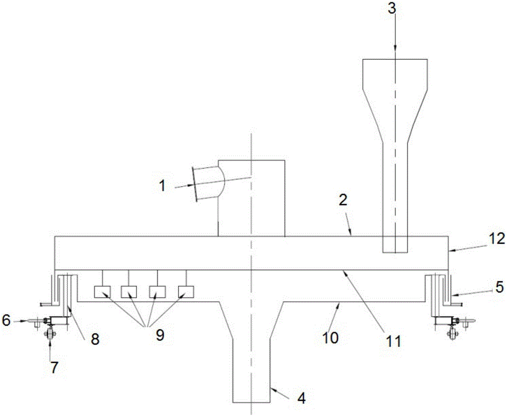
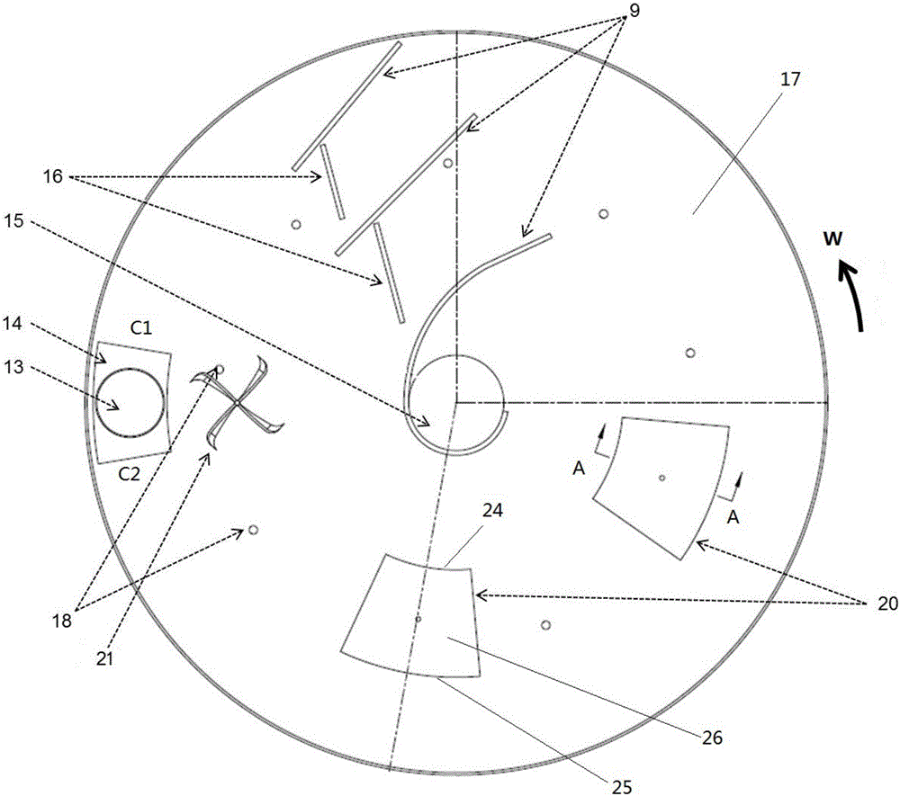
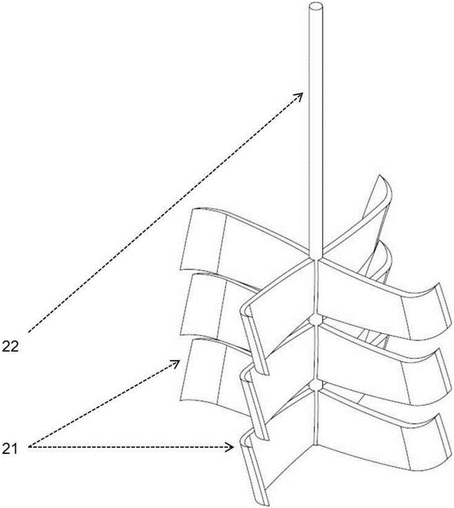
The invention discloses a rotary disc reactor which comprises a rotary tray (10), a reactor shell and a mixing mechanism. The mixing mechanism comprises a rotary shaft (22) and rotary blades (21). The rotary shaft is suspended above the surface (17) of a carrying material; the rotary blades are mounted on the rotary shaft and can be driven to rotate to stir and mix a material layer stacked on the surface of the carrying material. As the mixing mechanism with the rotary blades is additionally arranged, the mixing effect can be enhanced, so that the rotary disc reactor is particularly suitable for heating with a solid heat carrier or a pyrolyzation condition of a sticky material, coal materials can be mixed in situ at an appointed position of the tray, the solid-solid phase mixing degree and the inter-phase heat transfer effect are enhanced, the thick material layers can be mixed in different deep positions, pyrolyzed gas escapes from the depth of the material layers, and the holding capacity of the tray is increased and the pyrolyzed gas yield is increased. In particular, the rotary blades are driven by means of a rotary force of the rotary tray without affecting the moving track and the standing time distribution of materials.

Description

technical field [0001] The invention relates to a reactor with a rotating tray, in particular to a rotating disk reactor for processing solid carbonaceous materials. Background technique [0002] Coal graded refining technology and complete sets of equipment are important research directions for realizing clean and efficient utilization of coal. The rotary disc solid heat carrier coal pyrolysis reactor is the core equipment of coal classification refining, and its main research and development goals are large-scale, high efficiency and low cost. [0003] Coal medium-low temperature pyrolysis has received extensive attention since the 1970s and 1980s, and a variety of pyrolysis processes have been developed. According to the heating method, it can be divided into two types: external heating and internal heating. The thermal efficiency of the external heating process is low, the heating is uneven, and the secondary decomposition of volatile products is serious; the internal h...

Claims


Application Information

Patent Timeline
Patent Type & Authority Applications(China)
IPC IPC(8): B01J19/18B01J19/28C10B49/16C10B53/00C10B53/04C10B53/06C10B53/07C10B55/04
CPCB01J19/0053B01J19/0066B01J19/18B01J19/28C10B49/16C10B53/00C10B53/04C10B53/06C10B53/07C10B55/04Y02P20/143
Inventor 吴昌宁陈微李君顾佥秦强麻林郭屹
Owner CHNA ENERGY INVESTMENT CORP LTD
Learn More