Stator floating iron core locating and tensioning device and stator floating iron core installing method

A technology of tensioning device and stator core, which is applied in the field of stator floating core installation and positioning and tensioning device of stator floating core, which can solve the problems of bending deformation of iron core and failure of stator floating core to float, etc. The effect of press-fitting quality and small force

Inactive Publication Date: 2015-07-15
湖南云箭科技有限公司
View PDF5 Cites 7 Cited by
  • Summary
  • Abstract
  • Description
  • Claims
  • Application Information

AI Technical Summary

Problems solved by technology

[0005] In order to overcome the defects of the prior art, the present invention provides a positioning and tensioning device for the floating iron core of the stator of a hydroelectric generator and an installation method for the floating iron core of the stator, so as to solve the problem that th

Method used


Image

  • Stator floating iron core locating and tensioning device and stator floating iron core installing method
  • Stator floating iron core locating and tensioning device and stator floating iron core installing method
  • Stator floating iron core locating and tensioning device and stator floating iron core installing method

Examples


Embodiment Construction

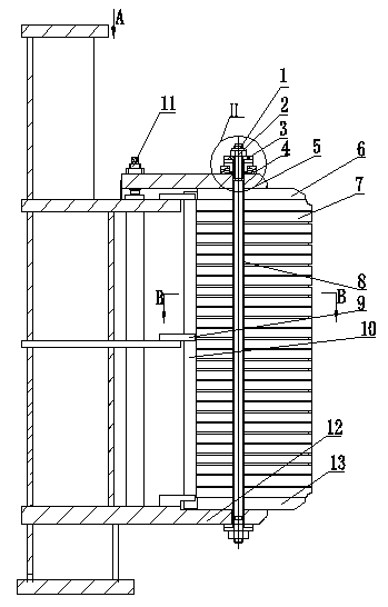
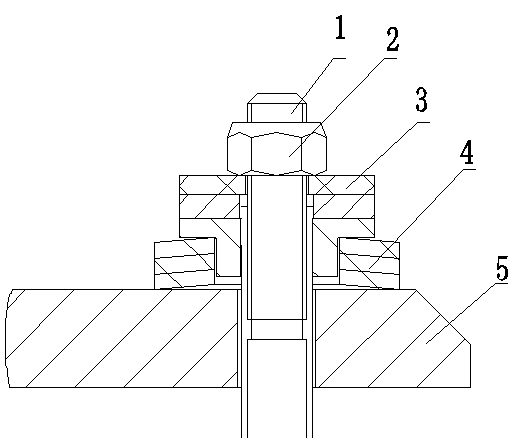
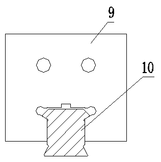
[0020] Such as Figure 1 to Figure 4 In the positioning and tensioning device for the stator floating iron core of the hydro-generator shown, the base ring plate 12 is connected to the stator base, the lower tooth pressure plate 13 is installed on the base ring plate 12, and several stator core pieces 7 are stacked on the upper gear Between the pressure plate 6 and the lower tooth pressure plate 13, the stator pressure plate 5 is located on the side of the upper tooth pressure plate 6 away from the stator core sheet 7, the stator pressure plate 5 is connected with the stator base through the stator core adjustment screw 11, and several through-holes for fastening The screw 1 runs through the stator pressure plate 5, the upper tooth pressure plate 6, the stacked stator core sheet 7, the lower tooth pressure plate 13 and the base ring plate 12 in sequence, the core-through screw 1 is covered with an insulating sleeve 8, and the two ends of the core-through screw 1 are respectivel...


PUM


Abstract

The invention provides a stator floating iron core locating and tensioning device and a stator floating iron core installing method. The stator floating iron core locating and tensioning device comprises an engine base ring plate (12), a lower tooth support (13), an upper tooth support (6), stator iron core chips (7), a stator pressing plate (5), through bolts (1), double dove-tail bar supporting plates (9) and double dove-tail bars (10). The through bolts (1) penetrate through the stator pressing plate (5), the upper tooth support (6), the stacked stator iron core chips (7), the lower tooth support (13) and the engine base ring plate (12). Each through bolt (1) is sleeved with an insulating sleeve (8). Locking nuts (2) are arranged at the two ends of each through bolt (1) respectively. The upper end of each through bolt (1) is sleeved with a belleville spring (4) and a bolt insulating spacer (3). The two ends of the double dove-tail bars (10) are connected with the double dove-tail bar supporting plates (9) and the stator iron core chips (7) respectively. The two ends of the stator iron core chips are bonded into one, and therefore in the iron core press-fitting process, iron cores are heated after being pressed under a cold state, and then pressed again under a hot state.

Description

technical field [0001] The invention relates to the field of hydraulic generators, in particular to a positioning and tensioning device for a stator floating iron core of a hydraulic generator, and also relates to a method for installing the stator floating iron core of a hydraulic generator. Background technique [0002] The diameter of the stator core of large and medium-sized hydro generators is large, the number of stator punches is large, and the heat of the stator is large. Under the action of mechanical vibration, electromagnetic comprehensive action and temperature change, the stator core will become loose; and the stator core and the frame There is a temperature difference between them, and the thermal expansion of the iron core produces pressure on the machine base, causing the iron core to bend and deform, affecting the normal operation of the generator. [0003] The stator core of the traditional large and medium-sized hydraulic generator adopts the following str...

Claims


Application Information

Patent Timeline
IPC IPC(8): H02K15/02
Inventor 周祥德
Owner 湖南云箭科技有限公司
Why Eureka
Try Eureka