Use of common public radio interface over asymmetric networks

A radio interface and asymmetric transmission technology, applied in wireless communication, electrical components, multiplexing communication, etc., can solve problems such as inability to estimate one-way delay

Inactive Publication Date: 2015-07-15
TELEFON AB LM ERICSSON (PUBL)
View PDF5 Cites 0 Cited by
  • Summary
  • Abstract
  • Description
  • Claims
  • Application Information

AI Technical Summary

Problems solved by technology

[0005] However, when the link uses an asymmetric connection, where the uplink delay is not necessarily equal...

Method used


Image

  • Use of common public radio interface over asymmetric networks
  • Use of common public radio interface over asymmetric networks
  • Use of common public radio interface over asymmetric networks

Examples


Embodiment Construction

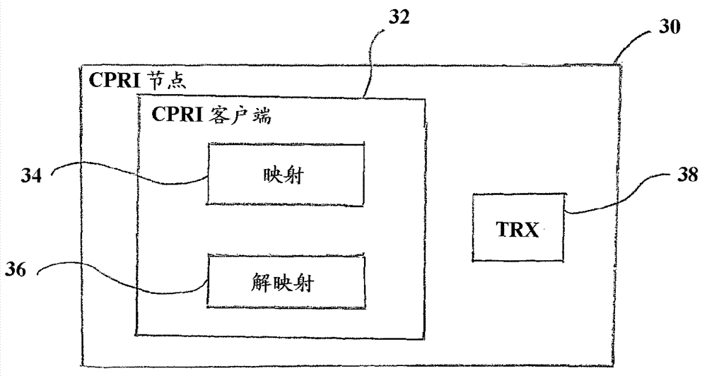
[0025] figure 1 Shown is the system architecture of a radio base station system 10, which is divided into two basic subsystems, namely radio equipment control (REC) and radio equipment (RE). As known, the REC contains the radio functions in the digital baseband domain, while the RE contains the analog RF functions. It will be appreciated that there are many system architectures and topologies in which interfaces according to the Common Public Radio Interface (CPRI) specification can be used. However, in figure 1 In the example system architecture shown, there is a single radio equipment control (REC) 12 connected to a first radio equipment (RE) 14 and a second radio equipment (RE) 16 . A radio equipment control (REC) 12 is connected to a first radio equipment (RE) 14 by means of a first CPRI link 18, the radio equipment control (REC) 12 acting as a master and the first radio equipment (RE) 14 acting as a slave. A first radio equipment (RE) 14 is connected to a second radio ...


PUM


Abstract

Communication between a Radio Equipment Control (REC) and a Radio Equipment (RE) in a wireless network uses a Common Public Radio Interface connection. When the Radio Equipment Control and the Radio Equipment are located remote from each other, and are connected by an asymmetric transport network, such as an Optical Transport Network, path delay data is transmitted in the Common Public Radio Interface data frames. This allows the CPRI end nodes to correct for path delay asymmetry using the path delay data.

Description

technical field [0001] The present invention relates to radio interface architectures, and in particular to radio access architectures using a common public radio interface. More specifically, the invention relates to the use of a common public radio interface over a transmission medium in which the downlink delay and uplink delay cannot be guaranteed to be equal. Background technique [0002] It is known that in a Radio Access Network (RAN), such as a Universal Mobile Telecommunications System (UMTS) RAN, a radio base station has two basic subsystems, namely Radio Equipment Control (REC) and Radio Equipment (RE). The Common Public Radio Interface (CPRI) defines specifications for the internal interface of a radio base station between the Radio Equipment Control (REC) and the Radio Equipment (RE). [0003] In some cases, a particular radio access network may require that the nodes of the network should synchronize within a specified time. In such cases, it will often be ne...

Claims


Application Information

Patent Timeline
IPC IPC(8): H04J3/06H04W88/08
CPCH04J3/1652H04L43/0864H04J3/065H04J2203/0082H04J3/0682
Inventor S.鲁菲尼B.波尔曼
Owner TELEFON AB LM ERICSSON (PUBL)
Why Eureka
Try Eureka